The Hunt For A Rare Version Of IBM’s OS/2

Slovenian OS/2 Warp 4 was a popular OS choice in that European country back in the day, but could the Slovenian Computer Museum lay their hands on a copy? In that question lies a bit of detective work and some luck.

There’s an old gag, about how this is finally the year of the Linux desktop. But oddly back in the ’90s it almost seemed possible, because alongside Microsoft Windows there were a host of other players that just might have become challengers. Foremost among them was IBM’s OS/2, a desktop PC operating system that could very much give Windows a run for its money. It could even run 16-bit Windows applications thanks to the code-sharing deal between the two companies dating back to the DOS days. Big Blue were so anxious to take their OS into new markets that they localized it into languages which Microsoft hadn’t touched, of which Slovenian was one.

But a couple of decades later, could a copy of this rare operating system version be found? While it may still lurk on a dusty shelf in an IT office somewhere it’s proved elusive, and online sources have dried up. The quest for it makes interesting reading for anyone with an interest in that period of retrocomputing, and finally ended up at the Slovenian company which had performed the localisation. This resulted in a copy of the OS, but not of the media, box, or paperwork. It yielded the fascinating discovery that IBM had localized the Windows 3.1-derived components as well as their own code, something that Microsoft had never done.

So do you have a boxed Slovenian OS/2 Warp 4 on a dusty shelf? Someone at the Slovenian Computer History Museum might like to see it. Meanwhile it’s a surprise to find that OS/2 is still supported.

Arduino Nano Powers Reverse Polish Notation Calculator

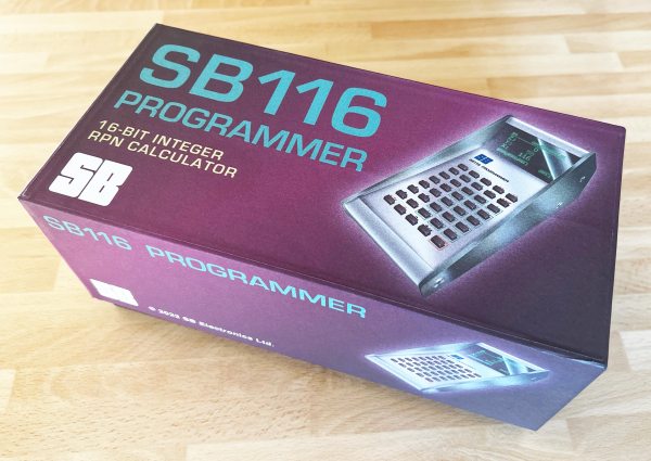
There’s something about Reverse Polish Notation (RPN) and the calculators that use it. It calls to mind a time when a calculator was a serious tool, and not just a throwaway toy. Created in the legacy of such calculators by HP and Texas Instruments, [Simon Boak] shows off his SB116, sporting an Arduino Nano under the hood. It’s a fully custom design, with a hand-built metal case, a custom PCB for the keyboard, and a tiny OLED display for maximum retro green goodness.

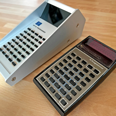
The impetus for this build was to replace a particular calculator, a well-used TI Programmer, that’s useful for working with 6502 assembly. The SB116 supports binary, octal, decimal, and hex; and boasts some downright useful functions — AND, NOT, OR, XOR, and bitshifts. The source code is available, but you’re on your own for the case and keyboard. And for maximized retro faux-nostalgia, [Simon] designed a box that would have looked right at home on an 80s store shelf.

Stick around for more retro-modern takes on calculators, or tales of repairing a genuine vintage model.

Git Intro For Hardware Hackers

Git is a wonderful tool that can multiply your project’s impact, or make your project easier to manage by an order of magnitude. Some of us hackers don’t yet know how to use command-line Git, but a relatable example of why a certain tool would be useful might be a good start. Today, I’d like to give you a Git crash course – showing you why and how to put a KiCad PCB into a Git repository, later to be shared with the world.

KiCad works wonderfully with Git. The schematic and PCB files of KiCad are human-readable, especially when compared to other PCB file formats. KiCad creates different files for different purposes, each of them with a well-defined role, and you can make sense of every file in your project folder. What’s more, you can even modify KiCad files in a text editor! This is exactly the kind of use case that Git fits like a glove.

Not Just For Software Developers

What’s Git about, then? Fundamentally, Git is a tool that helps you keep track of code changes in a project, and share these changes with each other. Intended for Linux kernel development as its first target, this is what it’s been designed for, but it’s flexibility extends far beyond software projects. We hardware hackers can make use of it in a variety of ways – we can store PCB and other design software files, blog articles, project documentation, personal notes, configuration files and whatever else that even vaguely fits the Git modus operandi. Continue reading “Git Intro For Hardware Hackers”

The Philly Maker Faire Is Back And Wants Your Hacks

After two years of waiting out the COVID-19 pandemic, the Philadelphia Maker Faire is officially back for 2022. The one-day event will take place on Saturday, the 15th of October, from 10:00 am to 5:00 pm at the Independence Seaport Museum.

We don’t have a schedule or full list of what will be on display this far out, but given what we saw during our 2019 visit, we’re confident you’ll get your tickets worth. While we keenly felt the loss of the flagship Maker Faires in California and New York, we can take some solace in the fact that their absence has given these smaller Faires a chance to move in and grow in ways that might not have been possible before.

For those looking to take an active role in what’s often been called the “Greatest Show & Tell on Earth”, organizers will be accepting proposals until September 15th for individuals, groups, and companies that want to share their creations with attendees. Participation is free, so long as you aren’t trying to sell anything, and offers a fantastic way to show off those pandemic projects. That said, proposals aren’t limited to just hardware projects — artwork, live performances, and workshops will also be considered. Basically, if it’s something the STEAM crowd would be interested in checking out, consider it fair game.

If you can spare some time after seeing everything that will be on display at the Maker Faire, the Independence Seaport Museum itself sounds like a pretty fascinating place to check out. Beyond the exhibits and collection of maritime artifacts, the Seaport also offers the chance to take tours aboard a pair of unique vessels: the USS Olympia saw service in the Spanish–American and First World Wars, and USS Becuna is one of only eight surviving WWII Balao-class submarines currently available for public viewing.

Planning on attending the 2022 Philadelphia Maker Faire? Maybe even presenting? Let us know in the comments. Who knows, you might just run into a Hackaday writer in the wild and score yourself some coveted Wrencher stickers.

Robotic Surgeons Are Showing Hints Of One Day Outperforming Humans

When it comes to fields that are considered the most complex of human endeavours, the most typically cited are those of rocket science and brain surgery. Indeed, to become a surgeon is to qualify in a complex, ever-changing, and high-performance field, with a pay scale and respect to match.

The tools of surgery have changed over time, with robotic assistants becoming commonplace in recent decades. Now the latest robots are starting to outperform human surgeons in some ways. Let’s look at how that’s been achieved, and what it means for the future of medicine. Continue reading “Robotic Surgeons Are Showing Hints Of One Day Outperforming Humans”

Finally We Can Watch The Deere Cracking Def Con Talk

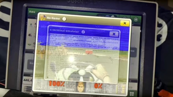
A few weeks ago, some tantalizing social media posts emerged from a Def Con talk, in which [Sick Codes] broke into the screen control unit for a John Deere tractor live on stage, and proceeded to play a special Deere-themed DOOM level upon it. At the time there was nothing more to go on, but we’re pleased to find out that the whole talk has been put online.

The talk starts with an introduction to the topic, to the basics of the control units within the machine and to the various different ages of Deere screen unit. We find that the earlier machines, which are still at work on farms worldwide, rely on outdated Windows CE versions, though the very latest screens run a Linux variant.

It’s one of these last screens to which he turns his attention, and we’re treated to an in-depth look at some of its secrets. After a lot of dead ends and learning exercises the final result is distilled into a pogo pin adapter for the hardware part, and a simple enough cron job to bypass one of Deere’s defenses by keeping the filesystem writable so a file can be updated. There’s a bit more detail about the special DOOM level too, as a special bonus.

You can see our original mention of this talk, or read some of our past Deere coverage.

Continue reading “Finally We Can Watch The Deere Cracking Def Con Talk”

What Every PCB Designer Needs To Know About Track Impedance With Eric Bogatin

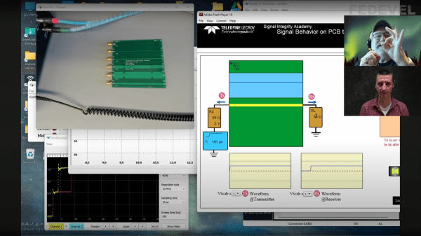
PCB design starts off being a relatively easy affair — you create a rectangular outline, assign some component footprints, run some traces, and dump out some Gerber files to send to the fab. Then as you get more experienced and begin trying harder circuits, dipping into switching power supplies, high speed digital and low noise analog, things get progressively more difficult; and we haven’t even talked about RF or microwave design yet, where things can get just plain weird from the uninitiated viewpoint. [Robert Feranec] is no stranger to such matters, and he’s teamed up with one of leading experts (and one of this scribe’s personal electronics heroes) in signal integrity matters, [Prof. Eric Bogatin] for a deep dive into the how and why of controlled impedance design.

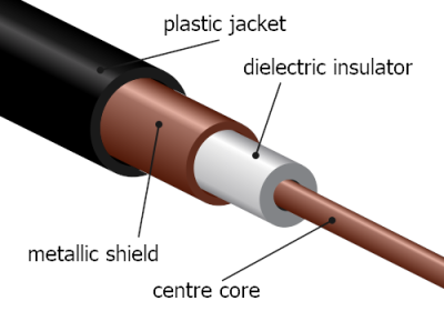
RG58 cable construction. These usually are found in 50 Ω and less commonly these days 75Ω variants

One interesting part of the discussion is why is 50 Ω so prevalent? The answer is firstly historical. Back in the 1930s, coaxial cables needed for radio applications, were designed to minimize transmission loss, using reasonable dimensions and polyethylene insulation, the impedance came out at 50 Ω. Secondarily, when designing PCB traces for a reasonable cost fab, there is a trade-off between power consumption and noise immunity.

As a rule of thumb, lowering the impedance increases noise immunity at the cost of more power consumption, and higher impedance goes the other way. You need to balance this with the resulting trace widths, separation and overall routing density you can tolerate.

Another fun story was when Intel were designing a high speed bus for graphical interfaces, and created a simulation of a typical bus structure and parameterized the physical constants, such as the trace line widths, dielectric thickness, via sizes and so on, that were viable with low-cost PCB fab houses. Then, using a Monte Carlo simulation to run 400,000 simulations, they located the sweet spot. Since the via design compatible with the cheap fab design rules resulted often in a via characteristic impedance that came out quite low, it was recommended to reduce the trace impedance from 100 Ω to 85 Ω differential, rather than try tweak the via geometry to bring it up to match the trace. Fun stuff!

We admit, the video is from the start of the year and very long, but for such important basic concepts in high speed digital design, we think it’s well worth your time. We certainly picked up a couple of useful titbits!

Now we’ve got the PCB construction nailed, why circle back and go check those cables?

Continue reading “What Every PCB Designer Needs To Know About Track Impedance With Eric Bogatin”