The first remote control for a TV was the Zenith Space Command back in the 1950’s. Space Command used sounds at ultrasonic frequencies to control the set. It wasn’t until the 1980’s and the Viewstar cable box that infrared entered the picture. Remote controls spread like wildfire. It wasn’t long before every piece of consumer electronics had one. Coffee tables were littered with the devices. It didn’t take long for universal remotes to hit the scene. [Woz] himself worked on the CL9 Core device, back in 1987. Even in today’s world of smart TV’s and the internet of things, universal remotes are still a big item. Hackers, makers, and engineers are always trying to build a device that works better for them. This week’s Hacklet is about some of the best universal and IR remote projects on Hackaday.io!
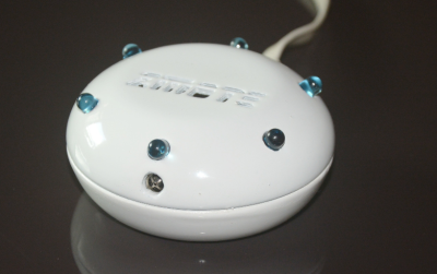 We start with [Harikrishna] and zmote. Zmote is an open source WiFi enabled, infrared, 360° remote control. That’s a mouthful. It might be easier to say it’s an ESP8266 and some IR LEDs. An ESP-01 module connects the device to WiFi and provides the 32-bit processor which runs the show. Learning functionality comes courtesy of a TSOP1738 modulated infrared receiver. The beauty of the Zmote is in the software. REST and MQTT connectivity are available. Everything is MIT licensed, and all the code is available on Github.
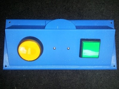
Next up is [Benjamin Kenobi] with TV Remote Control, Limited. Not everyone can operate the tiny buttons on a modern remote. [Benjamin] built this device for Easton, a special kid with a disability that impairs his motor skills. The 3D printed case holds two buttons – one for power, and one to change the channel. An Arduino Nano running [Ken Shirriff’s] IR library is the brains of the operation. The IR signal timing is hard coded for simplicity. One problem [Ben] ran into was the Nano’s high current draw, even in sleep mode. Batteries wouldn’t last a week. A simple diode circuit with a reed relay keeps the Nano shut down until Easton presses a button.
 Next we have [Nevyn] with OpenIR – Infrared Remote Control. A dead DSLR remote shutter release was all the motivation [Nevyn] needed to start work on his own universal remote control. OpenIR can be connected to (and controlled by) just about anything with a UART – a PC via an FTDI cable, a Bluetooth module, even an ESP8266. The module can be programmed by entering pulse length data through a custom Windows application. The Windows app even allows the user to view the pulses graphically, like a scope. The data is stored on an EEPROM on OpenIR’s PCB. Once programmed, the OpenIR board is ready to control the world.
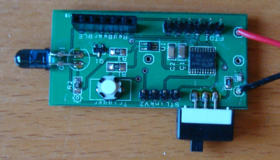
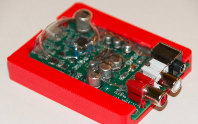
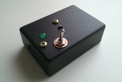 Finally, we have [facelessloser] with One button TV remote. This project may be the simplest open source remote control this side of TV-B-GONE. He wanted to build a simple remote control for his young daughter to scan between the various kids channels. A simple toggle switch turns the device on, and one button performs the rest of the magic. [Facelessloser] wanted to “move up” from an Arduino to an ATtiny85. This project became part of his ATtiny education. A custom PCB from OSH Park ties things together. A simple black project box keeps the electronics safe from tiny fingers – at least until she’s old enough to use a screwdriver.
If you want to see more IR and universal remote��projects, check out our new infrared and universal remote projects list. See a project I might have missed? Don’t be shy, just drop me a message on Hackaday.io. That’s it for this week’s Hacklet, As always, see you next week. Same hack time, same hack channel, bringing you the best of Hackaday.io!


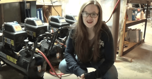
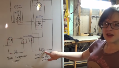 The Arduino’s GPIO pins can’t handle 9 amp AC loads, so [Hannah] wired them to TIP120 transistors. The TIP120s drive low power relays, which in turn drive high current air conditioning relays. The system works quite well, as can be seen in the video below the break.