Hackaday Reader [David] Wins A Camera From Make And Nikon


Make the shot fixed[David Schwarz] whipped up this moving time-lapse camera rig and won himself a sweet Nikon setup. You might remember our post about the Nikon Make:The Shot Challenge. [David] saw our post, and started thinking about what he wanted to enter. Like a true engineer, he finally came up with his idea with just 3 days left in the contest.

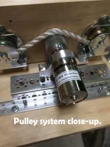
[David] wanted to build a moving time-lapse rig, but he didn’t have the aluminum extrusion rails typically used to build one. He did have some strong rope though, as well as a beefy DC motor with a built-in encoder. [David] mounted a very wide gear on the shaft of the motor, then looped the rope around the gear and two idler pulleys to ensure the gear would have a good bite on the rope. The motor is controlled by an Arduino, which also monitors the encoder to make sure the carriage doesn’t move too far between shots.

[6__pulley_systemDavid] built and tested his rig over a weekend. On Monday morning, he gave the rig its first run. The video came out pretty good, but he knew he could get a better shot. That’s when Murphy struck. The motor and controller on his rig decided to give up the ghost. With the contest deadline less than 24 hours away, [David] burned the midnight oil and replaced his motor and controller.
Tuesday morning, [David] pulled out his trump card – a trip to Tally Lake in Montana, USA. The equipment worked perfectly, and nature was cooperating too. The trees, lake, and the shadows on the mountains in the background made for an incredible shot. Once the time-lapse photos were in the can, [David] rushed home, stitched and stabilized the resulting video. He submitted his winning entry with just 2 hours to spare.

Click past the break for more on [David’s] time-lapse rig, and to see his final video.

Continue reading “Hackaday Reader [David] Wins A Camera From Make And Nikon” →

Thumbnail that say The Hacklet

The Hacklet #6 – Lasers

Hacklet 6

This week’s Hacklet is all about lasers, which have been shining a monochromatic light for hackers since 1960. The first working laser was demonstrated by [Theodore Maiman], who was a hacker / maker himself, having learned circuits in his father’s home electronics lab. It’s no surprise that lasers have been hugely popular in the hacker community ever since.

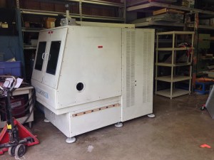
laserwelder[Maiman’s] first laser was pumped with flash tubes, which is similar to the YAG laser in [macona’s] project to restore a laser welder. He’s gotten his hands on a 1985 model 400W Lumonics laser welder. This welder was originally bought by Tektronix to weld titanium CRT flanges. Time moved on, and the welder was sold to [macona’s] company, who used it until the Anorad control system died. There was an effort to bring it up to date with new servos and an OpenCNC control system, but the job was never finished. This laser sat for 12 years before [macona] bought it, and now he’s bringing it back to life with LinuxCNC. The project is off to a blazing start, as he already has the laser outputting about 200 Watts.

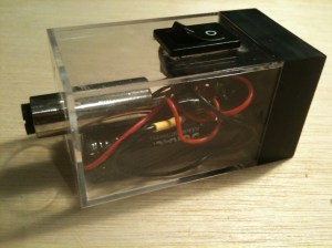
d0c96d91On the slightly lower power side of things we have [ThunderSqueak’s] 5mW visible red (650nm) laser. [ThunderSqueak] needed an alignment laser with decent focusing optics for her other projects. She mounted a module in a plastic case and added a switch. A quick build, but it’s paying dividends on some of her bigger projects – like her Low Cost CO2 Laser Build, which we featured on the blog back in May.


la-cutter

[phil] used buildlog 2.x as the inspiration for his Simple DIY laser cutter. The laser power comes from a low cost K40 laser tube and head. His frame is aluminum extrusion covered with Dibond, an aluminum composite material used in outdoor signs. Locomotion comes from NEMA 17 stepper motors. Many of [phil’s] parts are machined from HDPE plastic, though it looks like they could be 3D printed as well. We bet this one will be a real workhorse when it’s done.


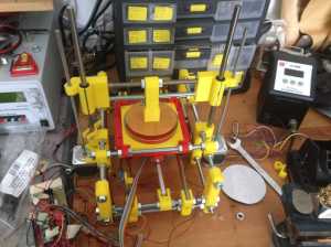
la-cutter2[ebrithil] is working on a combo laser engraver/PCB etcher which will use a solid state laser module. His layout is the standard gantry system seen on many other mills and 3D printers. Dual steppers on the Y axis increase avoid the need for a central belt. His Z axis was donated by an old DVD drive. It has enough power to lift a pen, and should be plenty accurate for focusing duty. He’s already run a couple of great tests with a low power violet laser and glow in the dark material.

openexposer[Mario] is creating an incredibly versitile laser tool in his OpenExposer, which can do everything from stereolithography 3D printing to making music as a laser harp. The genius here is [Mario’s] reuse of laser printer parts. Every laser printer uses the same basic setup: a laser, a scanning mirror, and optics to stretch the beam out to a full page width. [Mario] is already getting some great prints from OpenExposer. This project is one to watch in The Hackaday Prize.

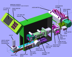
ramenspec[fl@C@] is digging into the physics side of things with his DIY 3D Printable RaspberryPi Raman Spectrometer. Raman Spectrometers are usually incredibly expensive pieces of requirement which can tell us which elements make up a given material sample. [fl@C@’s] laser is a 532nm 150mW laser, which bounces through a dizzying array of mirrors and lenses. The resulting data is crunched by a Raspberry Pi to give a full spectrographic analysis. [fl@C@’s] entered his project in The Hackaday Prize, and we featured his bio back in June.

That’s it for this week’s Hacklet, until next week, don’t just sit around wondering why aren’t lasers doing cool stuff. Make it happen, and post it up on Hackaday.io!


XOXO For The OCXO

HPocxo

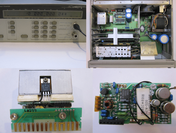
[Kerry Wong] recently got himself a frequency counter. Not just any counter, a classic Hewlett-Packard 5350B Microwave Counter. This baby will go 10Hz all the way up to 20GHz with only one input shift. A true fan of Hackaday Prize judge [Dave Jones], [Kerry] didn’t turn it on, he took it apart. In the process, he gave us some great pictures of late 80’s vintage HP iron.

Everything seemed to be in relatively good working order, with the exception of the oven indicator, which never turned off. The 5350B had three time bases available: a Thermally Compensated Crystal Oscillator (TCXO),  an Oven Controlled Crystal Oscillator (OCXO), and a high stability OCXO. [Kerry’s] 5350B had option 001, the OCXO. Considering it was only a $750 USD upgrade to the 5350B’s $5500 USD base price, it’s not surprising that many 5350B’s in the wild have this option.

[Kerry] checked the wattage of his 5350B, and determined that it pulled about 27 watts at power up and stayed there. If the OCXO was working, wattage would have dropped after about 10 minutes when the oven came up to temperature. Time to tear open an oven!

Armed with a copy of the 5350B service manual from HP’s website, [Kerry] opened up his OCXO. The Darlington transistors used as heaters were fine. The control circuit was fine. The problem turned out to be a simple thermal fuse. The service manual recommended jumping out the fuse for testing. With the fuse jumped, the oven came to life. One more piece of classic (and still very useful) test equipment brought back to full operation.

[via Dangerous Prototypes]

The Old Ping-Pong Ball Levitation Trick

pingpongLev

[Jacob] has put a slightly new twist on the levitating ball trick with his ping-pong ball levitation machine. We’ve all seen magnetic levitation systems before. Here on Hackaday, [Caleb] built a Portal gun which levitated a Companion Cube. Rather than go the magnetic route, [Jacob] levitated a ping-pong ball on a cushion of air.

Now, it would be possible to cheat here, anyone who’s seen a demonstration of Bernoulli’s principle knows that the ball will remain stable in a stream of air. [Jacob] proves that his system is actually working by levitating ping-pong balls with different weights.

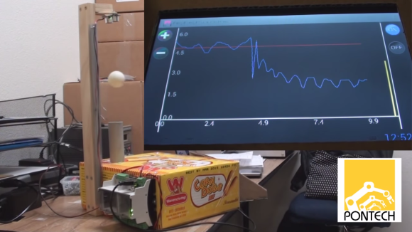
A Parallax Ping style ultrasonic sensor measures the distance between the top of the rig and the levitating ball. If the ball gets above a set distance, [Jacob’s] chipKit based processor throttles down his fans. If the ball gets too low, the fans are throttled up. A software based Proportional Integral Derivative (PID) loop keeps the system under control. A graph of the ball distance vs fan speed is displayed on an Android tablet connected to the controller via USB.

When [Jacob] switches a heavy ball for a light one, the lighter ball is pushed beyond the pre-programmed height. The controller responds by reducing the fan speed and the ball falls back. Who said you can’t do anything good with a box of corn dogs?

Continue reading “The Old Ping-Pong Ball Levitation Trick” →

Pocket Calculator Emulates Pocket Calculator

msp430 Calc Emu

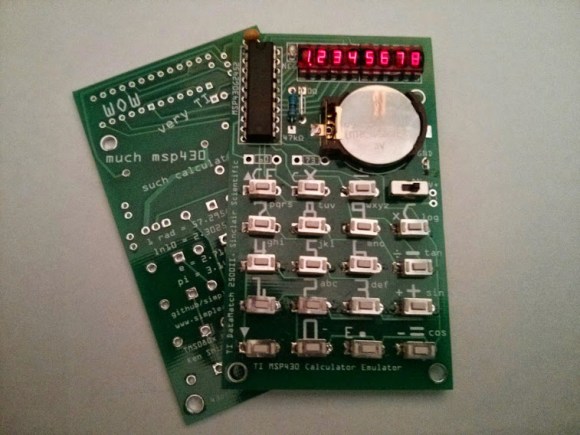
[Chris] has built a pocket calculator that emulates… a pocket calculator. Two pocket calculators, in fact. Inspired by [Ken Shirriff’s] incredible reverse engineering of the Sinclair scientific calculator, [Chris] decided to bring [Ken’s] Sinclair and TI Datamath 2500II simulators to the physical world.

Both of these classic 70’s calculators are based on the TMS0805 processor. The 0805 ran with 320 11-bit words of ROM and only three storage registers. Sinclair’s [Nigel Searle] performed the real hack by implementing scientific calculator operations on a chip designed to be a four function calculator.

[Chris] decided to keep everything in the family by using a Texas Instruments msp430 microcontroller for emulation. He adapted [Ken’s] simulator code to run on a MSP430G2452. 256 bytes of RAM and a whopping 8KB of flash made things almost too easy.[Chris’] includes ROMs for both the TI and the Sinclair calculators. The TI Datamath ROM is default, but by holding the 7 key down during boot, the Sinclair ROM is loaded. The silk screen includes key icons for both calculators, as well as some Doge-inspired wisdom on the back.

All joking aside, these really are amazing little calculators. Children of the 60’s and 70’s will be taken back when they see the LEDs flash as the emulated TMS0805 performs algorithmic arithmetic. [Chris’] code is up on Github. While he hasn’t released gerbers yet, he does have images of his PCB layout on the 43oh.com forums.

Continue reading “Pocket Calculator Emulates Pocket Calculator” →

[Tymkrs] Tombstone Guitar Amplifier

tymkrsTombstone

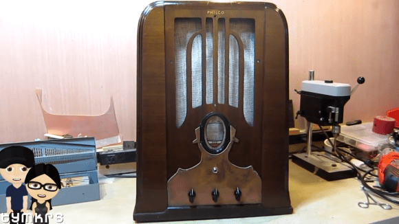
[Atdiy and Whisker], the team behind [The Tymkrs] YouTube channel, are at it again with a tombstone guitar amp project.(YouTube playlist link) Their amp began life as a Philco Tombstone radio which had seen better days. By the time [Tymkrs] got their hands on it, it was just a shell of its former self, as someone had already stripped all the electronics.

The amplifier itself is a disused Leslie tube amp [Tymkrs] had on hand. An LM386 serves as the pre-amp, making this a hybrid solid and vacuum state machine.

The tombstone speaker is especially interesting. [Tymkrs] went with an electrodynamic field coil speaker. Field coil speakers have no magnets, instead using a high voltage (approx 90V DC) coil to create a magnetic field for the voice coil to push against. This sort of speaker was commonplace in the 1930’s, as large magnets couldn’t be made lightweight enough to be used in a speaker. As magnet technology improved, permanent magnets became a staple in speakers.

[Tymkrs] paid special attention to the finish of the amplifier. They brought the tired old radio back to a high shine, then added a Metropolis inspired overlay from aged copper-clad board. The result is an amp that looks great and sounds great!

Continue reading “[Tymkrs] Tombstone Guitar Amplifier” →

Automatic Audio Leveling Circuit Makes Scanning More Fun

alan-scope1

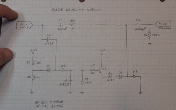
[Alan’s] friend came to him with a problem. He loved listening to his scanner, but hated the volume differences between stations. Some transmitters would be very low volume, others would nearly blow his speakers. To solve the problem, [Alan] built up a quick automatic leveling circuit (YouTube link) from parts he had around the lab.

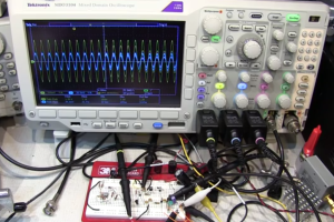
[Alan’s] calan-scope2ircuit isn’t new, he states right in the video that various audio limiting, compressing, and automatic gain control circuits have been passed around the internet for years. What he’s brought to the table is his usual flair for explaining the circuits’ operation, with plenty of examples using the oscilloscope. (For those that don’t know, when [Alan] isn’t building circuits for fun, he’s an RF applications engineer at Tektronix).



Alan’s circuit is essentially an attenuator. It takes speaker level audio in (exactly what you’d have in a desktop scanner) and outputs a limited signal at about 50mv peak to peak, which is enough to drive an auxiliary amplifier. The attenuator is made up of a resistor and a pair of 1N34A Germanium diodes. The more bias current applied to the diodes, the more they will attenuate the main audio signal. The diode bias current is created by a transistor-based peak detector circuit driven off the main audio signal.
But don’t just take our word for it, watch the video after the break.

Continue reading “Automatic Audio Leveling Circuit Makes Scanning More Fun” →