Restoring A Piece Of Musical History

Every restoration project involves various levels of grit, determination, gumption and doggedness. But [Darren Glen]’s restoration of a Jupiter-8 is an absolute labor of love. The Jupiter-8,  launched by Roland in 1981, was their flagship “polyphonic analog subtractive” synthesizer and was used by many legendary acts of the ’80’s. The synthesizer was rugged — built to withstand the rigors of travelling everywhere that the bands took it. More importantly, it could produce a wide range of sounds that came from dedicated and independent controllers. These, plus a host of other desirable features, makes the synth highly coveted even today and the rare ones that surface for sale can be quite expensive.

The back story of how he came in possession of this coveted, albeit non-functioning, piece of history is a good read. But the part that makes us all interested is the meticulous restoration that he is carrying out. There is a lot of useful information that he shares which could be handy if you are planning any restoration project of your own.

When he first turned it on, all he got was an “8” on the display — which seemed like an error code. From then onward, he has been carefully stripping away each part and slowly bringing it back to life. All of the linear slide potentiometers and slide switches were de-soldered, dis-assembled, cleaned of rust and the carbon tracks and contacts cleaned with special spray — making them almost as good as new. The transformer and its mounting brackets received a similar treatment of rust cleaning and fresh paint. All of the other internal metal parts, such as the chassis, were restored in a similar fashion.

White plastic buttons and knobs which were faded, were brightened up by spraying them with a generous dose of hydrogen peroxide hair spray, putting them in Ziploc bags and letting them bake in sunlight for a day. [Darren] was satisfied enough with this process and gave the same treatment to all the other colored buttons too, with good results. The other set of plastic parts – the keyboard keys, were cleaned and polished with a scratch and blemish polish cream, and replacements were ordered out from a specialist supplier for the few that were damaged beyond repair.

But by far the greatest challenge for [Darren] has been resurrecting the top metal cover. It was badly rusted and had to be completely stripped of all paint. Repainting it the right shade was relatively easy, but applying the legend and decals took him to every screen printer in town, none of whom could manage the job. He lucked out by locating a screen printer who specialized in custom automotive work and managed to do a pretty good job with the decal work.

The Z80 microprocessor had lost all its magic smoke, so [Darren] has ordered an original Zilog replacement which will hopefully clear the error he noticed when it was first turned on. He’s slowly working his way through all the issues, and it is still work in progress, but we look forward to when it’s all done and dusted. A fully functional, restored Roland Jupiter-8 — one of the first 500 that were built back in 1981 — resurrected with a lot of TLC.

A big shout out to [Tim Trzepacz] for bringing this project to our notice.

Pi Replaces Keiko-chan

[Tobias Kuhn] and a handful of colleagues at his workplace built Crystal Signal Pi, a Raspberry Pi based low-cost alternative for a notification device that provides visual, audio and network warnings about server problems. [Tobias] works for a Japanese company where it is critical for their servers to keep humming nicely all the time. Any emergencies or error conditions must be broadcast immediately so the technicians can fix it ASAP. Network enabled warning light stalks are used to provide these alerts. A local company produces a series of indicator and hazard warning lights which are colloquially called as Keiko-chan. These are similar to the hazard warning tower lights commonly fixed on machines on factory floors or many kinds of vehicles such as fork lifts. The Kieko-chans add a few bells and whistles making them more suitable for use in the server data centre — a Gigabit LAN port for wired networks and a USB port for WiFi modules. So, besides visual and audio warnings, it can also transmit messages over the network to alert the maintenance folks. Using this commercial solution should not have been a problem were it not for their rather hefty price tag of almost $500 per pop.

So [Tobias] decided to build his own warning lights based around the Raspberry Pi. After two rounds of prototypes, a simple HAT was designed that could be plugged in to a Pi. Details of the hardware are sketchy, but it’s simple enough to figure out. The part list consists of a PLCC-6 style RGB LED, three transistors to drive the three LED pins, a voltage regulator with a couple of electrolytic capacitors and a large push button. A simple acrylic case, and an acrylic cylinder mounted on top of the RGB LED creates a nice edge lit effect for the indicator.

The code for the Crystal Pi is hosted on Github, and includes handy scripts to make installation easy. Once installed, the Crystal Pi can be accessed and controlled either through a web-based GUI or via the API. There are some more interesting features already implemented or scheduled for later, so do check out the blog and the repository for more. Check out the video below to see the Crystal Pi in action.

Continue reading “Pi Replaces Keiko-chan”

MeatBagPnP Makes You The Automatic Pick And Place

It’s amazing how hackers are nowadays building increasingly complex hardware with SMD parts as small as grains of sand. Getting multilayer PCB’s and soldering stencils in small quantities for prototyping is easier than ever before. But Pick-and-Place — the process of taking parts and stuffing them on the PCB in preparation for soldering — is elusive, for several reasons. For one, it makes sense only if you plan to do volume production as the cost and time for just setting up the PnP machine for a small run is prohibitive. And a desktop PnP machine isn’t yet as ubiquitous as a 3D printer. Placing parts on the board is one process that still needs to be done manually. Just make sure you don’t sneeze when you’re doing it.

Of course the human is the slow part of this process. [Colin O’Flynn] wrote a python script that he calls MeatBagPnP to ease this bottleneck. It’s designed to look at a row in a parts position file generated from your EDA program and highlight on a render of the board where that part needs to be placed. The human then does what a robotic PnP would have done.

A bar code scanner is not necessary, but using one does make the process a bit quicker. When you scan a code on the part bag, the script highlights the row on the spreadsheet and puts a marker on the first instance of it on the board. After you’ve placed the part, pressing the space bar puts a marker on the next instance of the same value. The script shows it’s done after all parts of the same value are populated and you can then move on to the next part. If you don’t have a bar code scanner handy, you can highlight a row manually and it’ll tell you where to put that part. Check it out in the video below.

Of course, before you use this tool you need some prior preparation. You need a good PNG image of the board (both sides if it is double-sided) scaled so that it is the same dimensions as the target board. The parts position file generated from your EDA tool must use the lower left corner of the board as the origin. You then tell the tool the board dimensions and it scales up everything so that it can put the red markers at the designated XY positions. The script works for single and double-sided boards. For a board with just a few parts, it may not be worth the trouble of doing this, but if you are trying to manually populate a complex board with a lot of parts, using a script like this could make the process a lot less painful.

The project is still fresh and rough around the edges, so if you have comments or feedback to offer, [Colin] is listening.

[Colin]’s name ought to ring a bell — he’s the hacker who built ChipWhisperer which took 2nd Prize at The Hackaday Prize in 2014. The MeatBagPnP project is a result of having worked at building increasingly complex boards manually and trying to make the process easier. In addition to the walk-through of how the script works after the break we’ve embedded his other video from three years back when he was stuffing parts — including BGA’s — the hard way and then reflowing them in a Chinese oven with hacked firmware.

Continue reading “MeatBagPnP Makes You The Automatic Pick And Place”

Continuity Tester Uses The ATtiny85’s Comparator

There’s an inside joke among cyclists – the number of bikes you need is “n+1”, where “n” is your current number of bikes. The same probably also applies to the number of tools and equipment a hacker needs on their workbench. Enough is never enough. Although [David Johnson-Davies] has a couple of multimeters lying around, he still felt the urge to build a stand-alone continuity tester and has posted details for a super-simple ATtiny85 based Continuity Tester on his blog. For a device this simple, he set himself some tall design goals. Using the ATtiny85 and a few SMD discretes, he built a handy tester that met all of his requirements and then some.

The ATtiny85’s Analog Comparator function is perfectly suited for such a tester. One input of the comparator is biased such that there is a 51 ohm resistor between the input and ground. The output of the comparator toggles when the resistance between the other input and ground is either higher or lower than 51 ohms. Enabling internal pullup resistors in the ATtiny85 not only takes care of proper biasing of the comparator pins, but also helps reduce current consumption when the ATtiny85 is put to sleep. The test current is limited to 100 μA, making the tester suitable for use in sensitive electronics. And enabling the sleep function after 60 seconds of inactivity reduces standby current to just about 1 μA, so there is no need for a power switch. [David] reckons the CR927 button cell ought to last pretty long.

For those interested in building this handy tester, [David] has shared the Eagle CAD files as well as the ATtiny85 code on his Github repository or you could just order out some boards from OSHpark.

Modder Puts Computer Inside A Power Supply

When building a custom computer rig, most people put the SMPS power supply inside the computer case. [James] a.k.a [Aibohphobia] a.k.a [fearofpalindromes] turned it inside out, and built the STX160.0 – a full-fledged gaming computer stuffed inside a ATX power supply enclosure. While Small Form Factor (SFF) computers are nothing new, his build packs a powerful punch in a small enclosure and is a great example of computer modding, hacker ingenuity and engineering. The finished computer uses a Mini-ITX form factor motherboard with Intel i5 6500T quad-core 2.2GHz processor, EVGA GTX 1060 SC graphics card, 16GB DDR4 RAM, 250GB SSD, WiFi card and two USB ports — all powered from a 160 W AC-DC converter. Its external dimensions are the same as an ATX-EPS power supply at 150 L x 86 H x 230 D mm. The STX160.0 is mains utility powered and not from an external brick, which [James] feels would have been cheating.

For those who would like a quick, TL;DR pictorial review, head over to his photo album on Imgur first, to feast on pictures of the completed computer and its innards. But the Devil is in the details, so check out the forum thread for a ton of interesting build information, component sources, tricks and trivia. For example, to connect the graphics card to the motherboard, he used a “M.2 to powered PCIe x4 adapter” coupled with a flexible cable extender from a quaint company called Adex Electronics who still prefer to do business the old-fashioned way and whose website might remind you of the days when Netscape Navigator was the dominant browser.

As a benchmark, [James] posts that “with the cover panel on, at full load (Prime95 Blend @ 2 threads and FurMark 1080p 4x AA) the CPU is around 65°C with the CPU fan going at 1700RPM, and the GPU is at 64°C at 48% fan speed.” Fairly impressive for what could be passed off at first glance as a power supply.

The two really interesting take away’s for us in this project are his meticulous research to find specific parts that met his requirements from among the vast number of available choices. The second is his extremely detailed notes on designing the custom enclosure for this project and make it DFM (design for manufacturing) friendly so it could be mass-produced – just take a look at his “Table of Contents” for a taste of the amount of ground he is covering. If you are interested in custom builds and computer modding, there is a huge amount of useful information embedded in there for you.

Thanks to [Arsenio Dev‏] who posted a link to this hilarious thread on Reddit discussing the STX160.0. Check out a full teardown and review of the STX160.0 by [Not for Concentrate] in the video after the break.

Continue reading “Modder Puts Computer Inside A Power Supply”

Precision Voltage Reference Source

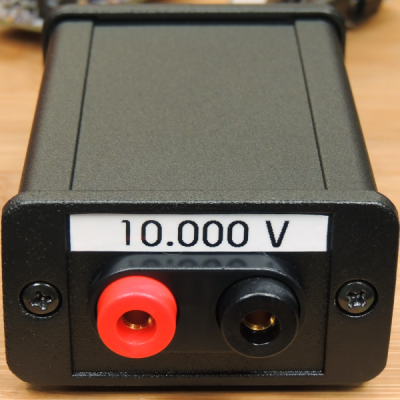
[barbouri] found a few old (vintage?) parts from the early ’80’s while rummaging through his parts bin, and quickly spun out a small PCB to build a 10.000 V reference using these old ICs. Throwing together a small number of parts, he was able to build a source which might be good enough to use as a reference for another circuit or provide a quick calibration check for some of his bench instruments that have a resolution of 1 mV or maybe even 100 μV.

The AD584* pin programmable precision voltage references have been available since the ’80’s and offer four programmable output voltages of 10.000 V, 7.500 V, 5.000 V, and 2.500 V. The chip is laser-trimmed to ensure high accuracy and low temperature coefficient and requires just a few external components to function. It is available in TO-99 hermetically sealed metal can and 8-pin DIP variants. The “S” version of the device that [barbouri] used provides a temperature coefficient of 30 ppm/°C max over a -55 °C to +125 °C temperature range but other versions of the chip offer a better stability. Analog Devices seem to have discontinued the “L” version (pdf), since it is no longer listed in the current data sheet, but you can still get them from a few sources. The “L” version has a temperature coefficient of just 5 ppm/°C.

Using quality parts such as high stability resistors and TO-99 PTFE socket with gold-plated contacts, his observations confirm that the unit is stable within 30 μV, with a very slow voltage increase of a few microvolts every 6 hours. A 15 V linear regulator powers the device with input power coming from an external wall wart. A small aluminum enclosure houses the device, with two gold-plated 4 mm sockets for the output. If you would like to build your own, his board design is hosted on OSH park, or you can download the Eagle CAD design files. He’s posted all links on his blog post, and provides part numbers for all of the parts used. [barbouri] has been doing a good job of building handy devices for his work bench – check out his well-built milli Ohm Meter that we had featured earlier.

A Look At Chinese Value Engineering

Seventy cents doesn’t buy you a lot these days. Maybe some sweets or candies at most. How about a string of LEDs that you can use to decorate your home during the festive season? [Amaldev] was curious to know what was, or wasn’t, inside these blinky LED strings which made them so cheap. He’s done a Christmas LED Light Teardown and shows how blinky LED string lights can be built with the bare minimum of components.

The string he purchased had 28 LEDs – seven each in four colors, a controller box with one push button and a  power cord. Without even knowing what is inside the controller box, the cost of the product seems astonishing based on this BoM. The single push button cycles through eight different light patterns for each press. It even has a faux CE mark for the supply plug. Cracking open the case, he finds that the controller board is sparsely populated with just seven through hole components and a COB (chip on board) module. A simple, 8-bit, 8-pin microcontroller is possibly what controls the device.

[Amaldev] sketches out a schematic to figure out how it works. There are two arms with 14 LEDs of alternating colors, each of which is controlled by an SCR. Two GPIO output pins from the COB control the gates of each of these SCR’s. The button is connected to a GPIO input, and a second input is connected to the AC supply via a current limiting resistor. Most likely, this is used to determine the zero crossing of the waveform so that the COB can generate the appropriate trigger signals for the gate outputs.

It is unlikely that these products are manufactured using automated processes. The PCB production could be automated, but soldering all the wires, fitting it all in the enclosure and preparing the LED string itself would require manual labor. At US$ 0.7 retail on the street, it is difficult to imagine the cost breakdown even when the quantities are in large numbers. Maybe a combination of cheap components, recycled or rejected parts (mains cord/enclosure), lack of safety and protection measures (no fuses, no strain reliefs) and reducing the component BoM to an absolute, bare minimum, coupled with very high volumes lets them pull it off? What are your thoughts – chime in with comments.