Taking Apart A Vintage Oscilloscope

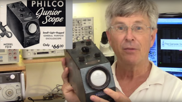
After getting a power supply and a multimeter, the next piece of gear a hacker would want to add to their bench is the oscilloscope. Nowadays, even the cheapest ones cost a few hundred dollars yet pack in the features. At the other end of the scale, if you can pony up close to a  million dollars, you can help yourself to an oscilloscope capable of 100 GHz bandwidth and 240 GS/s sampling rate. With that perspective, it becomes interesting to take a look at this video (embedded below), where [Jack Ganssle] shows us the Philco 7019 Junior Scope which was introduced way back in 1946. It seems the Philco 7019 model was an identical re-badged version of the Waterman Model S-10-A PocketScope.

[Jack] is familiar to all of us as an embedded systems engineer, but in this video he does a teardown of this vintage analog model. He starts off by walking us through the various controls, of which there are not a lot, in this “portable” instrument. At around the 3:40 mark in the video, he’ll make you wince as he uses a screwdriver and hammer combo to smash another ’40’s vintage CRT just so he can show us it’s innards — the electron beam source and the horizontal and vertical deflection plates. The circuit is about as bare-bones as it can get. Besides the CRT, there are just three vacuum tubes. One is the rectifier for the power supply, a second one is used for the vertical amplifier while the third one is the free running horizontal sweep oscillator. There is no triggering option — you just adjust the sweep frequency via a potentiometer as best you can. It does have internal, external and line frequency function selection, but it still requires manual adjustment of the sweep oscillator. There’s no blanking signal either, so the return sweep is always clearly visible. This is evident from the horizontal burn mark on the phosphor of the CRT after decades of use. It’s amusing to see that the vertical position could be adjusted by moving a magnet attached to the side cover.

The Oscilloscope Museum website hosts the Instruction Manual for this model, as well as a sales brochure which makes for very interesting reading after viewing [Jack]’s video.

Thanks, [Itay], for the tip.

Continue reading “Taking Apart A Vintage Oscilloscope”

Dummies Guide To Reverse Engineering

[Juan Carlos Jiménez] has reverse engineered a router — specifically, a Huawei HG533. While that in itself may not sound substantial, what he has done is write a series of blog posts which can act as a great tutorial for anyone wanting to get started with sniffing hardware. Over the five part series, he walks through the details of identifying the hardware serial ports which open up the doors to the firmware and looking at what’s going on under the hood.

The first part deals with finding the one or several debug ports on the hardware and identifying the three important pins – Rx, Tx and GND. That’s when he shows novices his first trick – shining a flashlight from under the PCB to find the pins that have trace connections (most likely Rx and Tx), those that don’t have any connections (most likely CTS and DTR) and those that have connections to the copper pour planes (most likely VCC and GND). The Tx signal will be pulled up and transmitting data when the device is powered up, while the Rx signal will be floating, making it easy to identify them. Finding the Baud rate, though, will require either a logic analyser, or you’ll have to play a bit of a guessing game.

Once you have access to the serial port and know its baud rate, it’s time to hook it up to your computer and use any one of the several ways of looking at what’s coming out of there — minicom, PuTTY or TeraTerm, for example. With access to the devices CLI, and some luck with finding credentials to log in if required, things start getting interesting.

Over the next part, he discusses how to follow the data paths, in this case, looking at the SPI signals between the main processor and the flash memory, and explaining how to use the logic analyser effectively and decode the information it captures. Moving further, he shows how you can hook up a USB to SPI bridge, connect it to the flash memory, take a memory dump of the firmware and read the extracted data. He wraps it up by digging in to the firmware and trying to glean some useful information.

It’s a great series and the detailed analysis he does of this particular piece of hardware, along with providing a lot of general tips, makes it a perfect starting point for those who need some help when getting started on debugging hardware.

Thanks, [gnif] for posting this tip.

Continue reading “Dummies Guide To Reverse Engineering”

Cheap LCD TV Gets Cheaper Fix

Most hacks need some fair bit of skill and knowledge if you want to come out successful at the other end. Others, you just plunge in blindly with a “heck, it’s already broken so I can’t make it any worse” attitude. Throwing caution to the wind, you dive in, rip things up, and see if you can manage to catch the bull by the horns.

[Jim]’s cheap LCD TV, barely a few years old, died. It was purchased from the store whose blue polo-shirted cashiers can drive you nuts with their incessant questions. [Jim] just rolled up his sleeves and rather haphazardly managed to fix his TV while adding an extra feature along the way.

His initial check confirmed that the LCD panel worked. Using a flashlight, he could see that the panel was displaying video which meant it was the backlight that wasn’t working. Opening up the TV, he located the LED driver board whose output turned out to be zero volts. [Jim] happened to have a lot of WS2812B strips lying around, along with their power supplies and RGB color controllers. The obvious solution was to ditch the existing LEDs and power supply and use the WS2812B strips.

Surprisingly, the original backlight consisted of just 21 LEDs arranged in three rows. He ripped those out, put in the WS2812B strips, and taped the jumble of wires out of sight. After putting it back together, [Jim] was happy to see it worked, although the new strips were not as bright as the old ones, causing some uneven light bands. He solved this by adding a few more strips of LEDs. It took him a couple of hours to fix his TV, but by the end of it, he had a TV whose backlight could be adjusted to any color using the external color controllers — although we’re not too sure what good that would be.

Huge Interactive Crossword

Give kids some responsible and challenging tasks, and you’d be surprised at the results. The “Anything Goes” exhibit at the National Museum in Warsaw was aimed as a museological and educational experiment. A group of 69 children aged 6–14 was divided into teams responsible for preparing the main temporary exhibition at the museum. Over six months, they worked on preparing the exhibition during weekly four-hour meetings. They prepared scripts, provided ideas for multimedia presentations, and curated almost 300 works for display. One of those was [Robert Mordzon]’s Giant Interactive Crossword.

The build is in two parts. The letter tiles, which have embedded RFID tags, obviously look like the easiest part of the build. The table, looking at the video (after the break), probably needed a lot more effort and labour. It is built in two halves to make construction easier. There are a 130 boxes that need to be filled in with the right letters to complete the crossword. Each box contains a bunch of electronics consisting of an Arduino Nano, a RFID Reader and a bunch of sixteen WS2812B LEDs, all assembled on a custom PCB. Do the math, and you’ll figure out that there’s 2080 LEDs, each capable of sipping 60 mA at full brightness. That’s a total current requirement of almost 125 amps at 5 V. Add in all the Arduino’s, and [Robert] needed a beefy 750 W of power, supplied via four switch mode power supplies.

Each Arduino Nano is a slave on the I²C bus. The I²C master is an Arduino Mega 2560, which in turn communicates with a computer over serial. When a box is empty, the LEDs are dim, when a wrong letter is placed, they turn Red, and when the right letter is placed, they turn Green. If a word gets completed, a special word animation is played. This information is also passed on to the computer, which then projects an animation related to the word on a giant wall screen. Upon the crossword getting completed, the table erupts in to a sound (via the computer) and light “disco” show and also reveals the main motto of this section of the exhibit – “Playing the Hero”.

Continue reading “Huge Interactive Crossword”

Ikea Standing Desk Goes Dumb To Smart On LIN Bus

IKEA’s products are known for their clean, Scandinavian design and low cost, but it is their DIY or “assemble it yourself” feature that probably makes them so popular with hackers. We seem to receive tips about IKEA hacks with a consistent regularity. [Robin Reiter] has a Bekant Sit/Stand motorized table with buttons to raise and lower the surface, but it doesn’t have any memory presets. That’s a shame because it requires a lot of fiddling with the up/down buttons to get it right every time. It would be nice to press a button, go grab a Coffee, and come back to find it adjusted at the desired height. With a little bit of hacking, he was able to not only add memory preset buttons, but also a USB interface for future computer control.

The existing hardware consists of a PIC16LF1938 micro-controller with two buttons for movement control and a LIN bus  protocol which communicates with the automotive grade motors with integrated encoders that report position values. After a bit of sniffing around with his oscilloscope and analyzer, he was able to figure out the control codes for the motor movements. For some strange reason, however, the LIN signals were inverted, so he had to introduce a transistor signal inverter between the PIC master and the Arduino Nano that would act as a slave LIN node. Software was made much easier thanks to an Arduino library developed by [Zapta] for the LIN Bus signal Injector, The controls now have four buttons — two to replicate the original up/down movements, and the other two to act as memory presets.

The code, schematic and a simple wiring layout are posted on Github, in case there are others out there who’d like to replicate this hack. Check out the video after the break where he gives a walk through the code.

Continue reading “Ikea Standing Desk Goes Dumb To Smart On LIN Bus”

Modular Portable Conveyor Belt

When teaching Industrial Automation to students, you need to give them access to the things they will encounter in industry. Most subjects can be taught using computer programs or simulators — for example topics covering PLC, DCS, SCADA or HMI. But to teach many other concepts, you  need to have the actual hardware on hand to be able to understand the basics. For example, machine vision, conveyor belts, motor speed control, safety and interlock systems, sensors and peripherals all interface with the mentioned control systems and can be better understood by having hardware to play with. The team at [Absolutelyautomation] have published several projects that aim to help with this. One of these is the DIY conveyor belt with a motor speed control and display.

This is more of an initial, proof of concept project, and there is a lot of room for improvement. The build itself is straightforward. All the parts are standard, off the shelf items — stuff you can find in any store selling 3D printer parts. A few simple tools is all that’s required to put it together. The only tricky part of the build would likely be the conveyor belt itself. [Absolutelyautomation] offers a few suggestions, mentioning old car or truck tyres and elastic resistance bands used for therapy / exercise as options.

If you plan to replicate this, a few changes would be recommended. The 8 mm rollers could do with larger “drums” over them — about an inch or two in diameter. That helps prevent belt slippage and improves tension adjustment. It ought to be easy to 3D print the add-on drums. The belt might also need support plates between the rollers to prevent sag. The speed display needs to be in linear units — feet per minute or meters per minute, rather than motor rpm. And while the electronics includes a RS-485 interface, it would help to add RS-232, RS-422 and Ethernet in the mix.

While this is a simple build, it can form the basis for a series of add-ons and extensions to help students learn more about automation and control systems. Or maybe you want a conveyor belt in your basement, for some reason.

Continue reading “Modular Portable Conveyor Belt”

Using SDR To Take Control Of Your Home Security System

[Dan Englender] was working on implementing a home automation and security system, and while his house was teeming with sensors, they used a proprietary protocol which was not supported by the open source system he was trying to implement. The problem with home automation and security systems is the lack of standardization – or rather, the large number of (often incompatible) standards used to ensure consumers get tied in to one specific system. He has shared the result of his efforts at getting the two to talk to each other via his project decode345.

The result enabled him to receive signals from Honeywell’s 5800 series of wireless products and interface them with OpenHAB — a vendor and technology agnostic open source automation software. OpenHAB offers “bindings” that allow a wide variety of systems and hardware to be integrated. Unfortunately for [Dan], this exhaustive list does not yet include support for the (not very popular) 345MHz protocol used by the Honeywell 5800 system, hence his project. Continue reading “Using SDR To Take Control Of Your Home Security System”