There are too many different kinds of displays – some of them, you already know. I’d like to help you navigate the hobbyist-accessible display world – let’s take a journey together, technology by technology, get a high-level overview of everything you could want to know about it, and learn all the details you never knew you needed to know. In the end, I’d like you to be able to find the best displays for any project you might have in mind, whatever it could be.
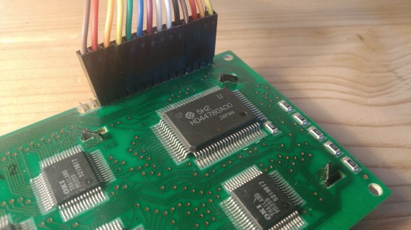
Today, let’s take a look at a well-known LCD technology – the HD44780 displays, a type of display that we hobbyists have been working with since the 1980s. Its name comes from the HD44780 driver chip – a character display driver IC that connects to a raw display panel and provides an easy interface.
HD44780 displays are not known for power efficiency, cutting-edge technology, ultimate flexibility, or small size, for that matter. However, they’re tried and true, easy to drive, require little to no computing power on your MCU, and you will be able to buy them for the foreseeable future. They’re not about to get taken off the market, and they deserve a certain kind of place in our parts boxes, too.
If you work with HD44780 displays for a project or two, you might acquire a new useless superpower – noticing just how many HD44780 displays are still in use in all sorts of user-facing devices, public or private. Going out and about in your day-to-day life, you can encounter a familiar 16 x 2 grid of characters in cash registers, public transport ticket machines, home security panels, industrial and factory equipment, public coffee machines, and other microcontroller-assisted places of all kinds! Continue reading “Displays We Love Hacking: The HD44780 Family”
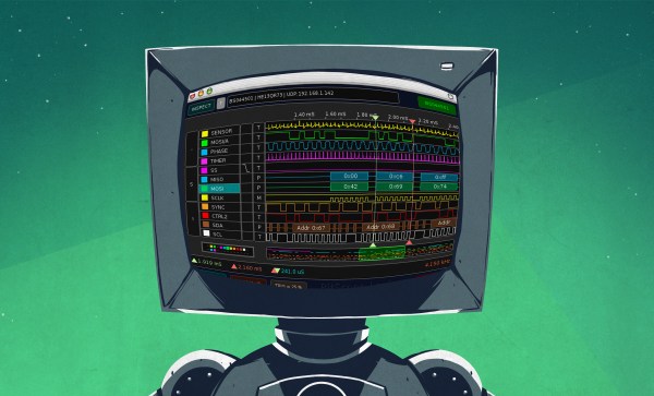
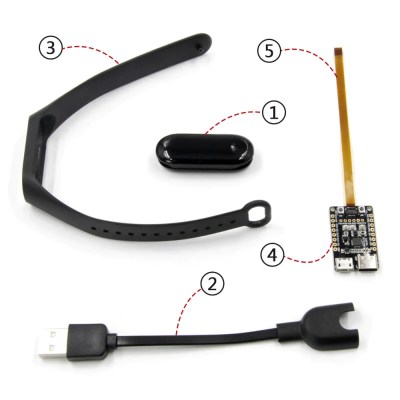 In this article, let’s figure out places where you can use a logic analyzer, and places where you can’t. We’ll start with the first limitation of logic analyzers – capture speed. For instance, here’s a cool thing you can buy on Aliexpress – a wristband from TTGO that looks like a usual fitness tracker, but has an ESP32 in it, together with an IMU, an RTC, and an IPS screen! The seller also has an FFC-connectable devboard for programming this wristband over UART, plus vibromotor and heartrate sensor expansion modules.