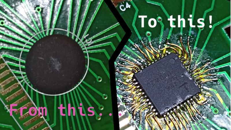
On the left, an image of a COB on the multimeter's PCB. On the right, a QFP IC soldered to the spot where a COB used to be, with pieces of magnet wire making connections from the QFP's pins to the PCB tracks.

Epoxy Blob Excised Out Of Broken Multimeter, Replaced With A QFP

The black blobs on cheap PCBs haunt those of us with a habit of taking things apart when they fail. There’s no part number to look up, no pinout to probe, and if magic smoke is released from the epoxy-buried silicon, the entire PCB is toast. That’s why it matters that [Throbscottle] shared his journey of repairing a vintage multimeter whose epoxy-covered single-chip-multimeter ICL7106 heart developed an internal reference fault. When a multimeter’s internal voltage reference goes, the meter naturally becomes useless. Cheaper multimeters, we bin, but this one arguably was worth reviving.

[Throbscottle] doesn’t just show what he accomplished, he also demonstrates exactly how he went through the process, in a way that we can learn to repeat it if ever needed. Instructions on removing the epoxy coating, isolating IC pins from shorting to newly uncovered tracks, matching pinouts between the COB (Chip On Board, the epoxy-covered silicon) and the QFP packages, carefully attaching wires to the board from the QFP’s legs, then checking the connections – he went out of his way to make the trick of this repair accessible to us. The Instructables UI doesn’t make it obvious, but there’s a large number of high-quality pictures for each step, too.

The multimeter measures once again and is back in [Throbscottle]’s arsenal. He’s got a prolific history of sharing his methods with hackers – as far back as 2011, we’ve covered his guide on reverse-engineering PCBs, a skillset that no doubt made this repair possible. This hack, in turn proves to us that, even when facing the void of an epoxy blob, we have a shot at repairing the thing. If you wonder why these black blobs plague all the cheap devices, here’s an intro.

We thank [electronoob] for sharing this with us!
Future Brings CPU Modules, And The Future Is Now

Modularity is a fun topic for us. There’s something satisfying about seeing a complex system split into parts and these parts made replaceable. We often want some parts of our devices swapped, after all – for repair or upgrade purposes, and often, it’s just fun to scour eBay for laptop parts, equipping your Thinkpad with the combination of parts that fits you best. Having always been fascinated by modularity, I believe that hackers deserve to know what’s been happening on the CPU module front over the past decade.

A Youtube thumbnail showing a Thinpad in the background with "Not Garbage" written over its keyboard, and one more keyboard overlaid onto the picture with "garbage" written on that one.
This “swap your Thinkpad keyboard” video thumbnail captures a modularity-enabled sentiment many can relate to.

We’ve gotten used to swapping components in desktop PCs, given their unparalleled modularity, and it’s big news when someone tries to split a yet-monolithic concept like a phone or a laptop into modules. Sometimes, the CPU itself is put into a module. From the grandiose idea of Project Ara, to Intel’s Compute Card, to Framework laptop’s standardized motherboards, companies have been trying to capitalize on what CPU module standardization can bring them.

There’s some hobbyist-driven and hobbyist-friendly modular standards, too – the kind you can already use to wrangle a powerful layout-demanding CPU and RAM combo and place it on your simple self-designed board. I’d like to tell you about a few notable modular CPU concepts – their ideas, complexities, constraints and stories. As you work on that one ambitious project of yours – you know, the one, – it’s likely you will benefit a lot from such a standard. Or, perhaps, you’ll find it necessary to design the next standard for others to use – after all, we all know there’s never too few standards! Continue reading “Future Brings CPU Modules, And The Future Is Now” →

Git Intro For Hardware Hackers

Git is a wonderful tool that can multiply your project’s impact, or make your project easier to manage by an order of magnitude. Some of us hackers don’t yet know how to use command-line Git, but a relatable example of why a certain tool would be useful might be a good start. Today, I’d like to give you a Git crash course – showing you why and how to put a KiCad PCB into a Git repository, later to be shared with the world.

KiCad works wonderfully with Git. The schematic and PCB files of KiCad are human-readable, especially when compared to other PCB file formats. KiCad creates different files for different purposes, each of them with a well-defined role, and you can make sense of every file in your project folder. What’s more, you can even modify KiCad files in a text editor! This is exactly the kind of use case that Git fits like a glove.

Not Just For Software Developers

What’s Git about, then? Fundamentally, Git is a tool that helps you keep track of code changes in a project, and share these changes with each other. Intended for Linux kernel development as its first target, this is what it’s been designed for, but it’s flexibility extends far beyond software projects. We hardware hackers can make use of it in a variety of ways – we can store PCB and other design software files, blog articles, project documentation, personal notes, configuration files and whatever else that even vaguely fits the Git modus operandi. Continue reading “Git Intro For Hardware Hackers” →

Lithium-Ion Batteries Are Your Friends

Need some kind of battery for a project? You can always find a few Lithium-Ion (LiIon) batteries around! They’re in our phones, laptops, and a myriad other battery-powered things of all forms – as hackers, we will find ourselves working with them more and more. Lithium-Ion batteries are unmatched when it comes to energy capacity, ease of charging, and all the shapes and sizes you can get one in.

There’s also misconceptions about these batteries – bad advice floating around, fearmongering videos of devices ablaze, as well as mundane lack of understanding. Today, I’d like to provide a general overview of how to treat your LiIon batteries properly, making sure they serve you well long-term.

What’s A Battery? A Malleable Pile Of Cells

Lithium-Ion batteries are our friends. Now, there can’t be a proper friendship if you two don’t understand each other. Lithium-Ion batteries are tailored for human needs by the factory that produced them. As for us hackers, we’ll want to learn some things.

First thing to learn – a single LiIon “unit” is called a cell. An average laptop contains three or six Li-Ion cells, a phone will have one, a tablet will have from one to three. What we refer to as “battery” is typically one or multiple cells, together with protection circuitry, casing and a separate connector – most of the time all three of these, but not always. The typical voltage is 3.6 V or 3.7 V, with maximum voltage being 4.2 V – these are chemistry-defined, the same for most kinds of cells and almost always written on the cell. Continue reading “Lithium-Ion Batteries Are Your Friends” →

The controller being held in its creator's hand after the modification's been done. The controller is painted in blue-white-black camo-like style. Analog sticks are sticking out where the buttons used to be

Oops! All Analog Sticks

Knowing his friend is a first-person shooter enthusiast, [Solderking] came up with a unique modified XBox controller as a gift. Tongue in cheek, you could argue that this controller is fully analog, as all of the buttons have been removed and replaced with analog sticks — each stick emulating four different buttons with its four different directions.

For this mod, he picked a controller known to have button connections available on testpoints. The controller’s buttons are digital inputs, but a bit of additional resistance wasn’t a problem for the IC in charge. Having tested that to be extra sure, he started the rebuilding work. As any self-respecting one-off mod, the bulk of this project involved JB Weld, point-to-point soldering of wires and taking a Dremel to the shell. That said, this project pays attention to detail, with portions of potentiometer track material carefully scraped off so that contact couldn’t be made in center position, and 3D printed spacers keeping the looks within the “gift-worthy” boundary.

After finishing the controller, [Solderking] tested it to confirm that it was absolutely atrocious to use, and breathed a sigh of relief, with yet another mod well done. We’ve already covered a few of his other fun efforts, like this Pokemon Ruby Nintendo cartridge restoration project where some delicate soldering was called for, or this broken mouse turned 12-key macropad.

Continue reading “Oops! All Analog Sticks” →

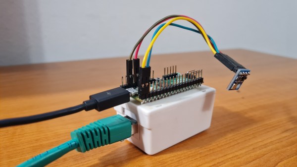
The Pi Pico board on top of a white box with an Ethernet jack, with a sensor module plugged onto the Pico's pin headers. A black MicroUSB and a green Ethernet cable are connected to this device.

An Elegant Ethernet Library For Your Next RP2040 Project

A few days ago we covered a project that brought Ethernet connectivity to the Raspberry Pi Pico using little more than some twisted pair and a RJ-45 connector. It was a neat trick, but not exactly ready for widespread adoption. Looking to improve on things a bit, [tvlad1234] has taken that project’s code and rewritten it into a friendly library you can use with any RP2040 board.

In case you missed it, the initial demo did 10BASE-T transmission by bit-banging with the PIO, and was able to send UDP messages to devices on the wired LAN. It was an impressive accomplishment, but its code didn’t make it easy to build your project around it. This new library makes UDP messaging as easy as a printf, offloading all non-PIO-managed Ethernet signal work onto the RP2040’s second CPU core. The library even generates a random MAC address out of your flash chip’s serial number!

As a demonstration of the new library, [tvlad1234] has put together a simple Ethernet-connected temperature monitor using the BMP085 or BMP180 sensor connect over I2C. If you feel like you could use an Ethernet transmit-only sensor in your life, browsing the source code would be a great start.

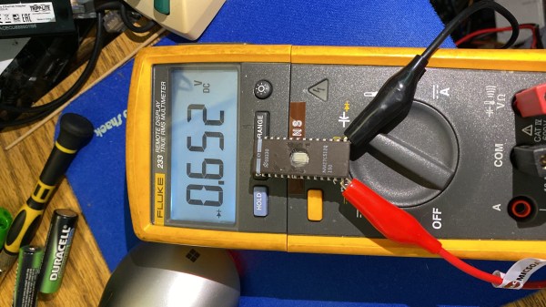
A multimeter connected to the EEPROM chip with crocodile clips, showing that there's a 0.652V diode drop between GND and one of the IO pins

Dead EPROM Dumped With Help Of Body Diodes

[Jason P], evidently an enjoyer of old reliable laser printing tech, spilled a drink (nitter) onto his Panasonic KX-P5400 SideWriter. After cleanup, everything worked fine — except that the PSU’s 5 V became 6.5 V during the accident, and the EPROM with LocalTalk interface firmware died, connection between VCC and GND seemingly interrupted inside the chip. Understandably, [Jason] went on Twitter, admitted the error of his ways, and sheepishly asked around for EPROM dumps.

Instead, [Manawyrm] wondered — would the chip have anti-ESD body diodes from GND to IO pins, by any chance? A diode mode multimeter check confirmed, yes! It was time for an outlandish attempt to recover the firmware. [Manawyrm] proposed that [Jason] connect all output pins but one to 5 V, powering the EPROM through the internal VCC-connected body diodes – reading the contents one bit at a time and then, combining eight dumps into a single image.

After preparing a TL866 setup, one hour of work and some PHP scripting later, the operation was a success. Apparently, in certain kinds of cases, dead ROM chips might still tell their tales! It’s not quite clear what happened here. The bond wires looked fine, so who knows where the connection got interrupted – but we can’t deny the success of the recovery operation! Need a primer on dumping EPROMs that are not dead? Here you go.

Continue reading “Dead EPROM Dumped With Help Of Body Diodes” →