XYZ Printing Unveils Inkjet-Based Filament Printer

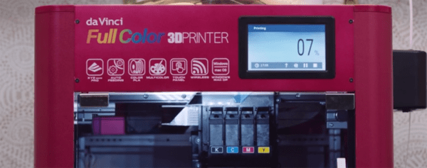
XYZ Printing, makers of the popular da Vinci line of 3D printers, have just released one of the holy grails of desktop 3D printing. The da Vinci Color is a full-color, filament based printer. How does this work? A special filament (Color PLA, although this filament is white in color) is extruded through a nozzle like any other 3D printer. Color is then added layer by layer by a system of inkjets in the head of the printer. Yes, it’s a full-color 3D printer, and yes, people have been suggesting this type of setup for years. This is the first time it’s been made real.

The specs for this printer are about what you would expect from any other filament-based printer in 2017. The build volume is 200 x 200 x 150mmm, the print bed has auto-leveling (although strangely doesn’t have a heated bed), and the user interface is a 5-inch color LCD. The da Vinci Color is available for preorder right now for $2,999.

You can check out a few pics of samples printed on the da Vinci Color below:

Continue reading “XYZ Printing Unveils Inkjet-Based Filament Printer”

Hackaday Prize Entry: An Open Source Kiln

For his Hackaday Prize entry, [Matt] is building a small kiln for melting metals and firing clay.  He’s making this kiln out of materials anyone can acquire — dirt and a bit of nichrome wire.

Most kiln builds you’ll find on the Internet use fancy refractory bricks and other materials you may not have in your back yard. [Matt]’s project is entirely DIY, and starts with a large pile of dirt and rocks. Aftter shaking off the sifted dirt, washing the rocks, straining off the gravel, getting rid of the sand, and siphoning off the water, [Matt] has a big bag of wet clay. This clay is mixed with perlite, an insulating, refractory material, molded into bricks, and fired. The result is a brick that looks good enough to be made into a kiln.

[Matt] has already put a lot of work into the calculations required to figure out the heat transfer of this kiln. At best, this kiln is going to take 14 hours to get up to temperature. That’s incredibly slow, but then again, this kiln will be electric, and will only use 1500 Watts. That’s nothing compared to a commercial electric kiln, but it is a build [Matt] designed himself without any outside help, using only parts he can easily acquire. In any event, this is an excellent project for the Hackaday Prize.

Friday Hack Chat: Making In Shenzhen

China is an amazing land of opportunity, and if you want to build anything, you can build it in Shenzhen. This city that was just a small fishing village a few decades ago has grown into a cyberpunk metropolis of eleven million and has become the manufacturing capital of the world. You’re probably reading this on a device made somewhere around Shenzhen.

For this week’s Hack Chat, we’re going to be talking about manufacturing in Shenzhen. We’re bringing in a very special guest for this one: [Naomi Wu] is a Cantonese DIY maker, professional web dev, transhumanist, electronics reviewer, occasional Hackaday contributor, vlogger, 3D printerer, advocate of women in STEM, SexyCyborg, and a riot on Twitter. [Naomi] also lives and works in Shenzhen, and is tapped into the DIY and maker culture there. She’s created 3D printed pen testing shoes, a Raspberry Pi cosmetics case, and infinity skirts.

This Friday (or Saturday, depending on which side of the date line you’re on), [Naomi] is going to be talking about manufacturing, making, DIY, and Shenzhen culture. Of particular interest will be electronics purchasing and manufacturing in Shenzhen, designing wearable projects with an emphasis on power and thermal design, documenting projects, and Shenzhen culture. This is basically an AMA, so if you have any questions you’d like to ask, throw them up in this spreadsheet.

Here’s How To Take Part:

join-hack-chatOur Hack Chats are live community events on the Hackaday.io Hack Chat group messaging. Hack Chats are usually at noon, Pacific time on Friday. This week we’re doing the Hack Chat a little later, because timezones. This week’s Hack Chat will be at 6 pm PDT Friday / 9 am CST Saturday. Confused? Here’s a time and date converter!

Click that speech bubble to the right, and you’ll be taken directly to the Hack Chat group on Hackaday.io

You don’t have to wait until Friday; join whenever you want and you can see what the community is talking about.

How To Do PCB Art In Eagle

Last month I had the pleasure of creating a new piece of hardware for Tindie. [Jasmine], the queen bee of Tindie, and I designed, developed, and kitted three hundred Tindie badges in ten days leading up to DEF CON. The badges were a complete success, they introduced soldering to a lot of people, and were loved by all.

This badge was such a rousing success, it’s now official Tindie swag. We’ll be handing out a few of these blinky badges at upcoming events. But as of right now we’ve already handed out our entire stock, that means we need to build more. The second run meant ordering a thousand PCBs.

We could just do another run, and order a few more PCBs from the Gerbers I’ve already designed. I’m not really happy with the first version of this badge, though, and this is an opportunity to improve my design. This also gives me an opportunity to demonstrate my workflow for creating artistic boards in Eagle.

Effectively, what I’ll be demonstrating here is the creation of the Benchoff Nickel. A few months ago, [Andrew Sowa] took a portrait of yours truly, changed the colors to what is available on a normal OSHPark PCB, and turned that into different layers in KiCad. There are a few differences here. Firstly, I’ll be using a blue solder mask, although the same technique can be applied to green, red, yellow, white, or black soldermask. Secondly, this is Eagle, and I’m going to do the majority of the work with a BMP import. This is the fast and easy way to do things; if you want a KiCad tutorial, check out [Andrew]’s work, or my overly-involved multiple silkscreen process for KiCad. I don’t recommend this overly-involved process if you can help it. It took 20 hours to do the art for my previous project in KiCad, and I estimate it would have taken two in Eagle.

With that said, here’s the easy, cheap, and fast way of doing artistic boards in Eagle.

Continue reading “How To Do PCB Art In Eagle”

Hackaday Prize Entry: A Manual, CNC Pick And Place Machine

Everyone who wants a 3D printer probably already has one, and even laser cutters and CNC machines are making their way into garages and basements ’round the world. Pick and place machines are the next great frontier of personal manufacturing, and even though that’s a long way off, [Tegwyn]’s project for this year’s Hackaday Prize is bringing us that much closer to popping down 0201 LEDs reliably.

This project is a manual pick and place machine — otherwise known as ‘tweezers’. It’s a bit more complicated than that, because the entire idea behind [Tegwyn]’s build is to decouple a human’s fine motor skills from the ability to place components on a board. To do that, this project is using an off-the-shelf, blue light special CNC machine. There’s not much to it, just a bit of aluminum extrusion and some threaded rods. However, with the addition of a vacuum pump, a hollow needle, and a few manual controls to move the axes around, the operator has very fine control over where a resistor, cap, or LED goes.

There are a few neat additions to the, ‘put a vacuum pump on a CNC machine’ idea. This is a 4 axis machine, giving the user the ability to rotate the part around a pad. There’s also a microscope hooked up to a small monitor mounted to the machine. If you’re assembling hundreds of boards, this is not the machine you want. If, however, you only need a handful, don’t mind spending a few hours placing parts, and don’t want to go insane with tiny QFN packages, this is a great build and a great entry for the Hackaday Prize.

Continue reading “Hackaday Prize Entry: A Manual, CNC Pick And Place Machine”

Retrocomputing With Open Source FPGAs

A few years ago, we saw the reverse engineering of the Lattice iCE40 bitstream, opening the door to a completely Open Source development tool chain for FPGAs. This was an astonishing amount of work from [Clifford Wolf], [Mathias Lasser], and [Cotton Seed], but since then we haven’t seen a whole lot from Project IceStorm. Now, that’s about to change, and in the coolest way possible. [hoglet] is retrocomputing on an ICE40 development board.

This is an implementation of the Acorn Atom on a myStorm BlackIce board. This board is basically just a Lattice iCE40 FPGA, a few support components, and a bunch of pin headers, some of which are in the not-so-handy Arduino pinout footprint. By porting some Acorn Atom implementations and a 6502 core to verilog, [hoglet] was able to stuff a cool old retrocomputer onto an Open Source FPGA development board. Video output is through a resistor DAC driving a VGA cable, and keyboard input is through PS/2.

Just about everything about this Open Source implementation of the Acorn works, and there’s still a lot left in the iCE40 FPGA. [hoglet] is able to run the 6502 core at 25MHz, which means just about every 6502-based system should be able to run on the BlackIce board.


Custom Cut Resistor Bandoliers

Through-hole resistors come on tape that we’re now calling bandoliers. Since [Spencer] is selling a boatload of his RC2014 backplane computer kits on Tindie, he’s been chopping up a lot of resistor bandoliers. It’s a boring and monotonous job.

Fortunately, a lot of people have had a bandolier cutting problem over the years, and there are some hobbyist-grade robots that will do this work for you. One of the more popular robots tasked for bandolier cutting is a laser cut robot. However, if you already have a laser cutter, why not just use the laser to cut the bandoliers? It’s brilliant in its simplicity.

[Spencer] spent a little bit of time designing a template to turn his laser cutter into a cutter for through hole resistors. No, he’s not trimming the leads — this is just a device to cut resistors into groups mini bandoliers of a handful of resistors. The tool is made out of plywood, with a smaller top piece held down with magnets to keep the resistors aligned.

The entire template is up on Thingiverse, and it’s great if you need to cut hundreds of resistors to kit dozens of projects. If you’re only doing one or two, scissors will be the way to go, but if you’re cursed with the monotony of trimming hundreds there’s no better way to get things done than to put a robot to work.