As a little experiment in desktop printing, because you can make a desk out of wood, [BlueFlower] modified a standard inkjet printer to print on wood. This is not an electronics mod by any means; this is still a printer that’s plugged into a USB port, does all the fancy printer firmware stuff, tells you to refill the yellow ink cartridge when you only want to print black, and all the other things that inkjet printer firmware will do. This is a mechanical mod. By taking apart the belts and rails and mounting them to a new frame, [BlueFlower] was able to open up the printer so a moving bed holding a board could be moved through the mechanics.
While the printer itself looks a little janky, you can’t argue with results. The prints look good, and should hold up well with a bit of finish. There’s a height adjustment for different thicknesses of stock, and if you’re exceptionally clever, you might be able to put a six-foot-long board through this thing. You can check out a video of this direct to wood printer in action below.
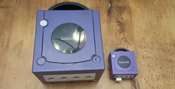
Casemodding, or stuffing video game consoles into shapes they were never meant to be in, is the preserve of a special breed. Our favorites are when old consoles are stuffed into different versions of the same console. Remember that gigantic O.G. Brick Game Boy carrying case? Yes, you can turn that into a jumbo-scale Game Boy, and it’s sweet. Continuining this trend of consoles of a different size, [Madmorda] has stuffed a GameCube into a sugar cube. It’s small. It’s really small, and it’s some of the best casemodding we’ve seen.
First off, the enclosure. This is an officially licensed micro GameCube case that originally housed gummy candies crafted by gummy artisans who work exclusively in the medium of gummy. This case, incidentally, is the perfect scale to match [Madmorda]’s earlier work, a miniaturized GameCube controller. This controller was originally a keychain, but with a bit of fine soldering skills it can indeed become a functional GameCube controller.
With the candy container GameCube gutted, the only task remaining was to put a GameCube inside. This is a lot easier if you tear down a Wii, and after desoldering, resoldering, and generally cutting up the circuit board of a Wii, [Madmorda] had something very small.
The finished console is a complete GameCube, compatible with all games, and no emulation. There are four controller ports, two USB ports for memory card slots, and output is composite through a 3.5mm jack. It’s a great piece of work and looks exactly like a miniaturized GameCube.
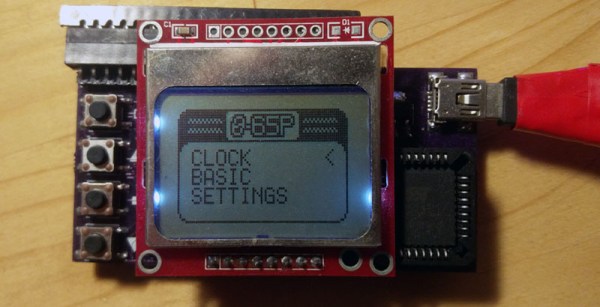
We are very familiar with retrocomputers, and if you want you too can build a computer that could have been made in the late ’70s on a breadboard. Just grab your CPU of choice, add some RAM, some ROM, a ton of jumper wires, and give it some way to talk to the outside world. The problem with the computers inspired by yesteryear is that they all, inexplicably, use through-hole parts. If only someone used the small QFP parts instead of the big chonkin’ PDIPs, we could have really small retrocomputers. That’s exactly what [NotArtyom] did, and he managed to come up with a wearable 6502 watch.
The system design for this 6502-based watch is fairly standard for what you would find in any other retrocomputer. There’s a PLCC 6502, 32k of SRAM, 16k of ROM, and a PLLC’d 6522 for a bit of IO. There are a few peripherals hanging off the 6522, and since this thing is a watch the most important is a real time clock. There’s also a Nokia LCD and a 20-pin Commodore keyboard connector.
Software-wise, most of the ROM is dedicated to G’Mon, a generic monitor that can view and modify memory. There’s also EhBasic, and a kernel to handle the RTC, keyboard, and display.
Whether or not this is a useful smartwatch isn’t the question; this is one of the first retrocomputer projects we’ve seen that lean into the non-PDIP versions of these classic chips. This is a bit surprising, because you can still buy these parts, PDIP or not, new from the usual vendors. If nothing else, it’s a demonstration of what can be done with modern IC packages.
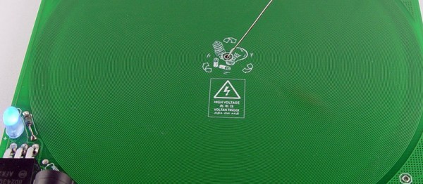
It’s badgelife season, and if you need an idea for a killer piece of wearable electronics, look no further than this PCB Tesla coil. Yes, it’s killer, doubly so if you’re wearing a pacemaker.
This project was inspired by an earlier Tesla coil on a PCB project that used 160 turns of 6 mil traces on a circuit board as the secondary. All the electronics are there, and it’s powered by USB. Plug this thing in, and you have a pocket full of lightning that’s approximately 30kV. It probably won’t kill you if you touch it, but let’s not test that too much. [Bobricious] took this idea and ran with it, stripping the circuit down to its bare minimum. Now it’s just a single transistor, with all the other parts printed on a circuit board.
There is one problem with making a Tesla Coil on a PCB, and that’s the number of turns on the coil. Any Tesla coil you’ll find is really just the clever application of a single thin wire wrapped around itself a few hundred or thousands of times. This Tesla coil is no different, and in this case it’s 240 turns of a single trace wrapping around a PCB that is 150mm square. [Bobricius] is one of the kings of putting tiny coils on a PCB, and his fiberglass brushless motor is a testament to that. We also just covered his circular linear motor raceway which also uses PCB coils.
The circuit is simple, just a power jack that accepts something around 20 Volts, a single BD243 transistor, an LED, and an 82k resistor. With that, you can lay a small neon tube on the PCB and watch it light up. With another PCB and another neon tube, this circuit board can transfer wireless power. It’s a fun toy, and it’s all PCB tech.
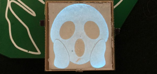
It’s that time of the year again, and once more we’re faced with the latest innovations in Badgelife, the movement to explore the artistic merits of electronics and manufacturing. This is an electroluminescent printed circuit board, and it’s some of the finest work we’ve seen. It’s also a Shitty Add-On that glows blue.
The process for applying an electroluminescent coating to printed circuit boards is, surprisingly, something we’ve covered before. Late last year, [Ben Krasnow] delved deep into a DIY EL display. The process is expensive, but all the products come from a company called Lumilor. The first step in this process is applying a thin conductive coating on a substrate with an airbrush. Since the entire idea of printed circuit boards is to have a layer of conductive material etched into any shape you want, the simple circuit board is the idea experimental platform for playing with EL displays. Traditionally, EL displays were made entirely with a silk screen process, like [Fran]’s ongoing attempt to recreate the Apollo DSKY display.
The electronics for this badge are simply a Microchip MIC4832 EL Driver, which converts the 3.something volts from the add-on header into 100 or so Volts AC at hundreds of Hz. This is a single-chip solution to driving EL displays, and the only other parts you need are an inductor, diode, and a few caps and resistors. An ATtiny85 can be used to blink the circuits, or, alternatively, you could copy [Ben]’s work and build a character EL display.
The process of applying an electroluminescent coating to a PCB does require a spray gun or airbrush, and the chemicals are a bit expensive. This, though, is pushing the boundaries of what can be done with artistic PCBs. It’s new applications of technology, simply as wearable electronics. It’s the best example of the possibilities of the medium and some of the best work that’s come out of the Badgelife scene.
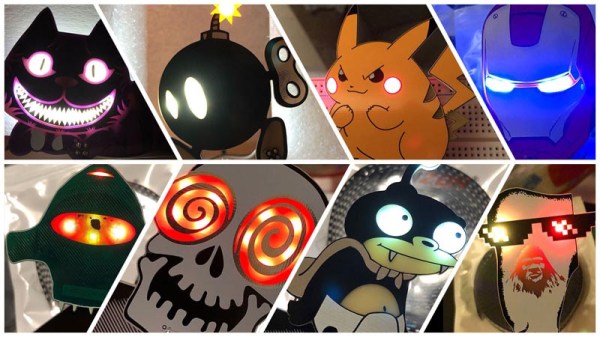
One of the most artistic applications of electrical engineering in recent memory is the burgeoning badgelife movement. This is an odd collective of people who are dedicating their time to rendering their own accomplishments in printed circuit boards. Of the entire badgelife collective, one of the most visible efforts are in Shitty Add-Ons, with a particular focus on reverse-mounted LEDs. Yes, you can install SMD LEDs upside down, and if you have your copper layers right, the light will shine through the badge.
One of the most prominent users of reverse mounted LEDs is [TwinkleTwinkie], and now finally we have a writeup on the science of reverse mounted LEDs. There’s a lot to unpack here, so buckle up and prepare to burn the tips of your fingers on a soldering iron.
For truly reverse-mounted PCBs, there are two options. The first, and most expensive, are ‘reverse gullwing’ LEDs. These LEDs are just like normal LEDs, except the SMD pads are reversed, allowing you to mount it so the light shines into the PCB. These LEDs are expensive, rare (only three companies make them), and they don’t really give off a lot of light. The other solution to reverse-mounting a LED is simply taking a standard 1206 SMD LED and manually soldering it upside-down. This is not pick and place friendly, although I’m sure you could find an LED manufacture that would put LEDs in reels upside-down if you want.
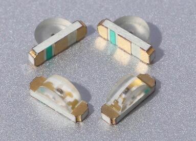
Side view LEDs
The takeaway for reverse mount LEDs is pick two: good, fast, or cheap. Reverse gullwing LEDs are expensive, but can be pick and placed and provide sufficient illumination. Hand-soldered LEDs installed upside down are cheap, slow, but also good.
But there is another option. Side view LEDs are a thing, and they can be pick and placed. You can get them in every color, and even UV. [Twinkle] has experimented with side-view LEDs in place of reverse mounted LEDs, and the results are promising. By putting the side view LED next to part of a PCB without copper or soldermask, there is some light bleed through the PCB. It’s somewhat uneven, but with a hot melt glue diffusor, you can get a somewhat decent bar of light being emitted through a PCB.
If you want to put blinky on a PCB, you have a lot of options. If you want to put blinky on a PCB without having any visible light source, these are your options. This is the state of the art in artistic PCBs, and we’re so glad [Twinkle] could share it with us.
If there’s one thing tiny Linux Systems on a Chip are good for, it’s emulation. There’s nothing like pulling out an emulation console on the bus for a quick game of old-school NES Tetris, or beating the next level in Super Mario World. This is the smallest emulation console ever. It’ll fit in your pocket, and it has a bright, vibrant screen. It doesn’t get better than this.
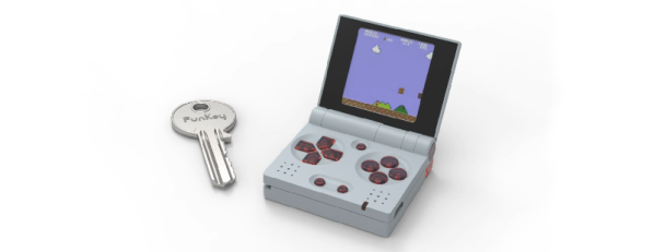
This project is an improvement on two projects, both of which are some of the top projects on hackaday.io, the best place on the Internet for hacks and builds. The Keymu is (or was, at the time) the smallest emulation console ever, built as a miniaturized version of the Game Boy Advance SP in a 3D printed case and powered by the Intel Edison. The Edison doesn’t exist anymore, so after that development moved over to the Funkey Zero, a tiny console built around the AllWinner V3s chip and a 240×240 display. Both of these are tiny, tiny consoles, but as silicon gets better there’s always better options, so it’s back to the drawing board.
The design of the Funkey Project is again built on the AllWinner V3S SoC with 64MB of DDR2 DRAM. There’s a 1.5″ display with 240×240 resolution, and of course this retro emulation console retains the classic and very useful clamshell form factor of the famous Game Boy Advance SP.
Already, this project is in the works and it’s shaping up to be one of the most popular projects on hackaday.io ever. Everyone wants an emulation console, and this is the smallest and tiniest one yet. Whether or not this project can carry through to production is another matter entirely, but we’re eager to find out.