Fire At Renesas Plant Fuels Chip Supply Woes

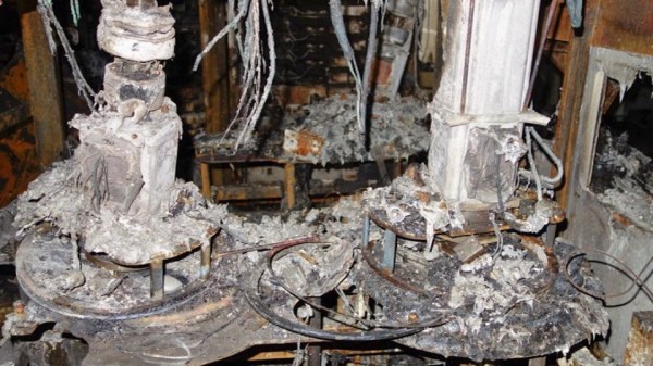
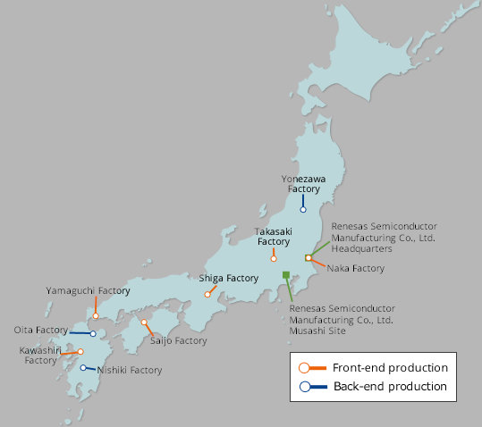
The small city of Naka (pop. 53K), a two-hour train ride from Tokyo on the eastern coast of Japan, was thrust into the international spotlight in the early dawn of Friday morning. A fire broke out among electroplating equipment in Renesas’s 300 nm N3 fabrication facility. It was extinguished before breakfast time, and fortunately nobody was injured nor were there any toxic chemical leaks. Only six hundred square meters on the first floor of the plant was damaged, but the entire building has to be closed for repairs. It will take approximately one month to restore normal operations, and CEO Hidetoshi Shibata is “concerned that there will be a massive impact on chip supplies”.

Renesas Naka Plant Location

In a press conference on Sunday afternoon, Renesas reports that the source of the fire has been determined, but the details are still unclear:

The casing of the equipment and the plating tank have relatively low resistance to heat, and the equipment ignited due to overcurrent. However, the cause of the overcurrent and the reason for the ignition is currently being investigated.

Semiconductors are already in short supply, as we reported back in January, forcing slowdowns at many auto manufacturers. The Naka plant primarily makes automotive semiconductors, worsening an already stressed supply chain. While the news focuses on the automotive sector, this shortage spills over into many other industries as well.

Continue reading “Fire At Renesas Plant Fuels Chip Supply Woes”

Arduino CLI For I/O Pin Testing

Need to quickly toggle or read some logic signals without the hassle of writing a quick program? [Thor_x86], aka [Eric], built an Arduino sketch that does just that — and he threw in the ability to send (or receive) serial messages, too. This is a neat idea — kind of a simplified Bus Pirate.

We should warn you that this is an early release, and there are a few minor issues which we are sure [Eric] will iron out soon. We discovered the function strtol() was misspelled in cmd_send.cpp, and there are some configuration #defines which need to be sorted out in file parsePin.cpp, depending on which Arduino module you are running. We got it running on an Arduino Leonardo the quickest, because it has support for Serial1().

Don’t be discouraged by these glitches in this rev 0 deployment — [Eric] has really made quite a nice tool here. Check his GitHub repository for updates (or submit corrections yourself). All in all, it’s a good addition to your digital tool box. On a completely unrelated note, we really like [Eric]’s USB cable with the right-angle micro connector, grungy though it may be.

Besides the standard tools like Bus Pirate, GreatFET, FTDI modules, etc., are there any similar tools you like to use for bit banging and serial testing? Let us know in the comments below.

Arduino Serial Vs SerialUSB

[Andrew] wonders why the SerialUSB() function on the Cortex M3-based Arduino Due is so much faster than Serial() on the Uno or Nano, and shares his observations in this short video. He sets up an experiment with a simple sketch on both boards and uses Wireshark to evaluate the results.

Data is sent in the USB packets in groups of four characters on the ATmega-based boards, but the entire string is put in a packet on the Due board. If you look under the hood, the answer is hiding in plain sight. While the Arduino family of boards connect to your computer using a USB virtual serial port, the ATmega ones have an actual serial connection on-board. For instance, on the Nano there is an FT232RL between the USB connector and the microprocessor (on an Arduino Uno board, a small ATMEGA8U2 is used instead of an FTDI chip, but the concept is the same). On the Arduino Due, the USB connects directly to the SAM3X8E processor.

This concept doesn’t apply only to Arduino boards, of course. On any serial connection between two computers, when a virtual USB device is used on both sides of the link (no actual serial signals involved), the serial baud rate is a fictional thing — data transfer speeds depends on USB alone. We are curious why the packets contain four characters in [Andrew]’s ATmega Wireshark captures — why not 1, 2, or 10? Is this something that can be controlled by the programmer, or is it fixed by the protocol and/or the FTDI chip? If you have the answer, let us know in the comments below. Continue reading “Arduino Serial Vs SerialUSB”

A Handy Reference For Display Drivers And LCD Controllers

Ever tried to find the data on a mysterious LCD controller that’s kicking around in your parts bin? Well check out this list of various LCD controllers that [Achim] has put together. He summarizes the basic specifications for each controller and includes data sheet links if available (note — the website is in German, although most of the data itself is in English). All in all, he has collected 72 controllers from five different manufacturers, and 46 of them have data sheets. For each controller, he tabulates maximum resolution, color depth, type of interface, and the targeted display technology. For example, here is the entry for the Ilitech ILI9341 TFT controller commonly found in embedded projects:

Furthermore, many of the controllers also have a short video clip showing them in operation posted over on [Achim]’s YouTube channel, where he also has a bunch of quick (less than one minute) videos of all sorts of embedded goodies. We do find this table of controllers to be a little dated — for example, another popular controller used on small color OLED displays, the Solomon Systech SDS1351, is not included. But it is certainly a good resource to bookmark.

We suspect that [Achim] made this table as a result of developing µGUI, a small (only three files) C-language graphics library (see the GitHub repository) he released back in 2015. Do you have any good resources for tracking down unknown LCD controllers? If so, share in the comments below. And thanks to [Dmitry] for sending in this tip.

Continue reading “A Handy Reference For Display Drivers And LCD Controllers”

LEGO Lunar Lander Animatronic Movie Released

Retired scientist [Mark Howe] spent the last couple months making an animatronic movie featuring his LEGO lunar lander in a video recreation of the Apollo 11 moon landing (also embedded below). [Mark] is not only the producer, but serves as the technical director, set designer, and cameraman as well. He designed and 3D-printed a custom special effects stage for the scene. It gives motion to the LEM using stepper motors, timing belts, pulleys, and a linear guide rod, all hidden inside a discrete upstage tower. He simulates the Lunar regolith using grout, spray adhesive, and a smattering of small rocks.

[Mark] implements the special effects sequencer in an Arduino Nano, and provides sound effects using an Adafruit audio sound board which he loaded up with sound files from the real Apollo 11 landing. Floor strip lighting is provided by an array of Neopixels, and a back-lit Earth is lowered from the fly space for one cut. He made a custom PCB motherboard to hold the Arduino, sound card and motor drivers.

The resulting production is quite impressive. This isn’t [Mark]’s first attempt to relieve the double boredom of both retirement and coronavirus isolation — back in December he produced a similar animatronic movie recreating a Saturn V launch. Thanks to [jhookie55] for the tip.

Continue reading “LEGO Lunar Lander Animatronic Movie Released”

Minimal UART Computer

[Carsten] spent over a year developing a small CPU system, implementing his own minimalist instruction set entirely in TTL logic. The system uses a serial terminal interface for all I/O, hence the term UART in the title. [Carsten] began building this computer on multiple breadboards, which quickly got out of hand.

He moved the design over to a PCB, but he was still restless. This latest revision replaces EEPROM with cheaper and easier to use CMOS Flash chips, and the OS gains a small file system manager. As he says in the video, his enemy is feature creep.

Tetris on the UART Computer

In addition to designing this CPU project, [Carsten] built an assembler and wrote a substantial operating system and various demo programs and games. He not only learned KiCAD to make this board, but also taught himself to use an auto-router. The KiCAD design, Gerbers, and BOM are all provided in his repository above. ROM images and source code are provided, as well as a Windows cross-assembler. But wait – there’s more. He also wrote a cycle exact emulator of the CPU, which, as he rightfully brags, comes in at under 250 lines of C++ code. This whole project is an amazing undertaking and represents a lot of good work. We hope he will eventually release the assembler project as well, in case others want to take on the challenge of building it to run under Linux or MacOS. Despite this, the documentation of the Minimal UART Computer is excellent.

[Carsten] claims the project has finally passed the finish line of his design requirements, but we wonder, will he really stop here? Do check out his YouTube channel for further informative videos. And thanks to [Bruce] for sending in the tip.

Continue reading “Minimal UART Computer”

A Discrete Logic Word Clock

Self-acclaimed computer nerd [Kevin Koster] was tired of designing new TTL-logic clocks before finishing his previous designs. So he finally buckled down and completed this unique word clock, which uses only a handful of TTL chips. We can’t disagree with his friends who complained that they can’t read [Kev]’s handwriting, so perhaps this diagram will make it clearer.

Besides being a nice logic-only project, this will give an example to younger folks how much effort went into things which are so simple to implement today. We don’t see a Karnaugh map on the project page for sorting out the logic diodes driving the minutes LEDs. If [Kev] did it on the fly, as the rat’s nest of diodes on the schematic would suggest, we’re not sure whether to scold him or be impressed (he does redraw that logic very neatly on a separate sheet).

No worries about high speed wiring on this project. The main oscillator derives time from the 50 Hz AC transformer power supply, and outputs a reference clock signal of 16.7 mHz (not MHz), or once per minute. This is divided down to 3.3 mHz for the 5-minutes counter and again to 277 uHz for the hour counter. If you live in a 60 Hz power mains country, you’d have to modify the oscillator section. Or you could contact [Kev] on his site, as he is considering making this available as a kit worldwide. If you like word clocks, we’ve covered quite a few of them before, including this crazy-complex rear-projection one.