Small Footprint Scara Laser Engraver Has Massive Build Area

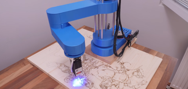
One of the limitations of the conventional Cartesian CNC platforms is that the working area will usually be smaller than its footprint. SCARA arms are one of the options to get around this, as demonstrated by [How To Mechatronics], with his SCARA laser engraver.

This robot arm is modified from the original build we featured a while back, which had a gripper mounted. It uses mainly standard 3D printer components with 3D printed frame parts. The arms lengths are sized to fold over the base and take up little table horizontal space when not in use. It can work in a large semi-circular area around itself, and if a proper locating and homing method is implemented, it can be moved around and engrave a large area section by section.

One of the challenges of SCARA arms is rigidity. As the cantilevered arm extends, it tends to lean over under its weight. In [How To Mechatronics]’s case, it showed up as skewed engravings, which he managed to mitigate to some degree in the Marlin firmware.

Another possible solution is to reduce the weight of the arms by moving the motors to the base, as was done with the Pybot or dual-arm SCARA printers like the RepRap Morgan.

Continue reading “Small Footprint Scara Laser Engraver Has Massive Build Area”

Making High Quality Copies Of Existing Parts Using A Silicone Mold

3D printing has made it incredibly easy to produce small runs of plastic parts, but getting rid of the 3D printed look can be tricky and time-consuming. When you need a smooth and polished finish, or you want to make exact copies of an existing injection molded part, casting resin parts in silicone molds is an excellent option. [Eric Strebel] has plenty of experience with the process, and demonstrates it in detail while creating copies of violin chin rests that are no longer in production. It’s an interesting application, where 3D-printed layer lines are not just an aesthetic issue, but something that would irritate the user’s skin if present.

Creating silicone molds requires a bit of forethought about the mold design. You want to select the split line to make it as easy as possible to remove the finished parts, while also placing the resin pouring sprue and vents to prevent air bubbles from getting trapped in the mold. In [Erics] case, it’s impossible to use a simple planar split line, so he mounts the master part on a block of wood and uses cardboard and modeling clay to create a volume where the second side of the mold will protrude in the first side. It’s important to note that sulfur-free clay must be used, otherwise the silicone might not cure.

One side of the silicon mold is cast first, and after curing it is placed back in the mold box with the master part to allow casting the other side of the mold. At this point [Eric] super glues the sprue-former and vent rods to the master parts before molding the second side. A release agent consisting of petroleum jelly and naphtha is added wherever the two sides of the mold will touch, to prevent them from sticking together.

Bubbles are your enemy while resin casting, so ideally you need a vacuum chamber to degas the silicone and resin before casting, and a pressure chamber to allow the resin part to cure. While pouring the silicone for the molds, the mold box is placed on a vibration table to allow any bubbles to rise to the surface. While the entire mold-making and molding process is time-consuming, the copied parts are almost indistinguishable from the original.

[Eric] has also shown us how to make much larger silicone molds in the past. If you find yourself making lots of different-sized mold boxes, it might be worth building an adjustable mold box.

Continue reading “Making High Quality Copies Of Existing Parts Using A Silicone Mold”

Pedal Operated Cable Cam For Hands Free Video

[Vintage Backyard RC] has built a nice little RC track in his backyard, and wanted a motorized dolly system to capture footage along the main straight with his GoPro. Using only junk box parts, he created a simple pedal operated RC cable dolly. (Video, embedded below.)

[Vintage Backyard RC] first experimented with a high speed car running on a length of model train track. However, it was bumpy at high speed, the track is expensive, and it needs 50 V running through the open tracks. The new cable cam gives a much smoother ride, and cost almost nothing with his supply of old RC gear. The cable cam is powered by a brushed motor from an RC airplane, running with plastic wheels on some weed trimmer line. Control is provided by an old 27 MHz RC system, with the controller’s internals transplanted into an old wah-wah guitar pedal.

The non-geared motor can drive the cable much faster than required, so [Vintage Backyard RC] needs to exercise some careful foot control to run it at a reasonable speed. This is easier said than done while also controlling an RC car with his hands, so he plans to replace the RC system with a newer 2.4 GHz system software end-point limits. We would be reaching for the ESP32 or any other microcontroller with wireless that we’ve come to know, but it’s worth remembering that most people are not familiar with these tools.

This is definitely the most minimalist cable cam we’ve covered this year, but just demonstrates how simple they can be to build. You can always upgrade to a sleek folding frame from 3D printed parts, and add machine vision and long range video streaming.

Continue reading “Pedal Operated Cable Cam For Hands Free Video”

Building An Archery Mech Suit To Skip Practice

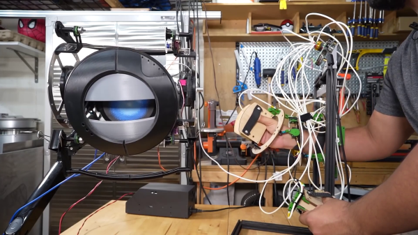
According to legend, King Edward III once said: “If you want to train a longbowman, start with his grandfather.” Consistently making accurate hits with any bow, especially on moving targets, takes many hours of practice. Or, if you’re [Shane Wighton], you can spend a comparable amount of time building, debugging, and rebuilding a robotically-enhanced bow to do it.

The goal was to shoot flying targets out of the air, so [Shane] had to create a system that could track the position of the bow and the target, and automatically adjust the position of the bow and loose the arrow at exactly the right moment to intercept the target. The position tracking was done with the same Optitrack cameras [Shane] used on his robotic basketball hoop, with reflective marking balls on the bow, target, and the release mechanism. The auto-aiming is done with a two-axis rack and pinion mechanism driven by a pair of stepper motors. [Shane] first used the cheapest recurve bow he could find online, which caused accuracy issues likely related to the Archer’s paradox. The setup also made him repeatedly hit himself in the face, because the servo-operated release mechanism would release unexpectedly without having a proper anchor with his draw hand.

[Shane] eventually upgraded to a compound bow, which reduced the tension he had to hold while lining up the shot, but also increased the weight of the system dramatically. This leads him to fully embrace the mech suit look, and use a Steadicam vest to hold the weight of the bow. This finally allowed him to reliably William Tell shots and hit the flying targets.

Whether it’s an all-in-one electronic golf club, an explosive baseball bat, or a robotic pool cue, [Shane] is certainly adept at using impressive engineering skills to compensate for his lack of physical skill, or just his willfully closed eyes. Continue reading “Building An Archery Mech Suit To Skip Practice”

Why You Can’t Make A Wearable Display With A Transparent OLED

After seeing the cheap transparent OLED displays that have recently hit the market, you might have thought of using them as an affordable way to build your own wearable display. To save you the inevitable disappointment that would result from such a build, [Zack Freedman] took it upon himself to test out the idea, and show why transparent wearable displays are a harder than it looks.

He put together a headband with integrated microcontroller that holds the transparent OLED over the user’s eye, but unfortunately, anything shown on the display ends up being more or less invisible to the wearer. As [Zack] explains in the video after the break, the human eye is physically incapable of focusing on any object at  such a short distance. Contrary to what many people might think, the hard part of wearable displays is not in the display itself, but rather the optics.  For a wearable display to work, all the light beams from the display need to be focused into your eyeball by lenses and or reflectors, without distorting your view of everything beyond the lens. This requires, lightweight and distortion-free collimators and beam splitters, which are expensive and hard to make.

While these transparent OLEDs might not make practical heads-up displays, they are still a cool part for projects like a volumetric display. It’s certainly possible to build your own smart glasses or augmented reality glasses, you just need to focus on getting the optics right.

From Tube And Wing To Just Wing: The Future Of Airliners

Airliners have become an unremarkable part of modern life, but unless you happen to be an aircraft enthusiast, you’d be forgiven for thinking the latest Airbus model looks more or less the same as the Boeing 707 that ushered in the Jet Age. But that might soon change, with blended wing airliners looking like the next step in air travel efficiency. In the video after the break, [Real Engineering] takes us on a fascinating tour of the past and possible future of jet airliners.

Contemporary airliners all still follow the same old “tube and wing” design, but have become vastly more efficient. The latest jetliners burn almost 50% less fuel per passenger-km than they did 50 years ago. This is thanks to better engines, improved aerodynamics, reduced weight, and a vast array of other, often invisible changes. However, it’s looking like a more drastic change is needed to keep the progress going, and NASA, Boeing, and Airbus are all betting on blended wing designs to do this.

Blended wing aircraft are basically flying wings, where the cargo-carrying section of aircraft is shorter, wider, and produces lift. This layout can be used to increase the aircraft’s internal volume, and improve aerodynamic losses, by eliminating the tail. Research shows that blended wing design could reduce fuel consumption by as much as 27%. Since load and produced lift are spread more evenly along the entire width of the aircraft, it also reduces the amount of structural reinforcement required for the wings, especially at the root. The large internal volumes also allow other power sources, like hydrogen fuel cells to be used.

Blended wing aircraft are not without challenges. They are inherently unstable and require complex control systems to fly. These control systems depend on sensors, actuators, and software to work properly, and require multiple levels of redundancy. The omission of these redundancies ultimately led to the 2008 crash of a B-2 bomber, and the more recent fatal crashes of Boeing’s 737 MAX airliners. Also, unlike tubular fuselages, blended wing designs are not ideal pressure vessels. However, this is not a major problem thanks to the availability of carbon composite materials to create strong, lightweight structures.

With aircraft technology moving as fast as ever, we look forward to seeing what the future will bring. Whether it’s personal rotorcraft or commercial space flight, it sure won’t be boring.

Continue reading “From Tube And Wing To Just Wing: The Future Of Airliners”

Helicopter Seed Robot Can Also Drop Like A Rock

Whether you know them as samara seeds, maple seeds, or helicopter seeds, most of us know the seeds that spin down to the ground on one or two blades. They have been served as the inspiration for several robotic autorotating gliders, and researchers from the Singapore University of Technology and Design (SUTD) can now also make them dive rapidly on command. Video after the break.

In the previous versions, researchers showed that they were able to steer the SAW (Samara Autorotating Wing) by actuating the trailing edge of the blade with a servo. It takes input from an onboard 3-axis magnetometer and GPS, and adjusts the control surface continuously depending on its orientation to make it fly in the chosen direction. The latest paper (PDF) focuses on the craft’s new ability to switch from autorotation to a rapid dive and back to autorotation. Named the dSAW (diving SAW), it can drop like a rock by changing the control surface angle to almost 90° the wing to stall it. It exits the dive by simply moving the control surface back to the normal autorotation position. The kinetic energy built up during the dive is converted to rotational energy very quickly, which slows its vertical velocity to almost zero for an instant before settling back into its normal glide.

We can certainly see this being useful where the dSAW needs to quickly lose altitude to avoid being pushed off-course by the wind. The video below demonstrates this by dropping three dSAWs from an RC airplane. On command, they spread out, each in its designated direction, and then repeatedly switch between dive and autorotation mode as they descend to the ground. The researchers envision this being used to scatter sensor units over a large area in a controlled fashion from a single aircraft. What would you do with this technology? Let us know below. Continue reading “Helicopter Seed Robot Can Also Drop Like A Rock”