Electric RC Plane Flies For Almost 11 Hours

Electric RC aircraft are not known for long flight times, with multirotors usually doing 20-45 minutes, while most fixed wings will struggle to get past two hours. [Matthew Heiskell] blew these numbers out of the water with a 10 hour 45 minute flight with an RC plane on battery power. Condensed video after the break.

Flight stats right before touchdown. Flight time in minutes on the left, and miles travelled second from the top on the right.

The secret? An efficient aircraft, a well tuned autopilot and a massive battery. [Matthew] built a custom 4S 50 Ah li-ion battery pack from LG 21700 cells, with a weight of 2.85 kg (6.3 lbs). The airframe is a Phoenix 2400 motor glider, with a 2.4 m wingspan, powered by a 600 Kv brushless motor turning a 12 x 12 propeller. The 30 A ESC’s low voltage cutoff was disabled to ensure every bit of juice from the battery was available.

To improve efficiency and eliminate the need to maintain manual control for the marathon flight, a GPS and Matek 405 Wing flight controller running ArduPilot was added. ArduPilot is far from plug and play, so [Matthew] would have had to spend a lot of timing tuning and testing parameters for maximum flight efficiency. We are really curious to see if it’s possible to push the flight time even further by improving aerodynamics around the protruding battery, adding a pitot tube sensor to hold the perfect airspeed speed on the lift-drag curve, and possibly making use of thermals with ArduPilot’s new soaring feature.

A few of you are probably thinking, “Solar panels!”, and so did Matthew. He has another set of wings covered in them that he used to do a seven-hour flight. While it should theoretically increase flight time, he found that there were a number of significant disadvantages. Besides the added weight, electrical complexity and weather dependence, the solar cells are difficult to integrate into the wings without reducing aerodynamic efficiency. Taking into account what we’ve already seen of [rcflightest]’s various experiments/struggles with solar planes, we are starting to wonder if it’s really worth the trouble. Continue reading “Electric RC Plane Flies For Almost 11 Hours”

Mechanical 7-Segment Display Uses A Single Motor

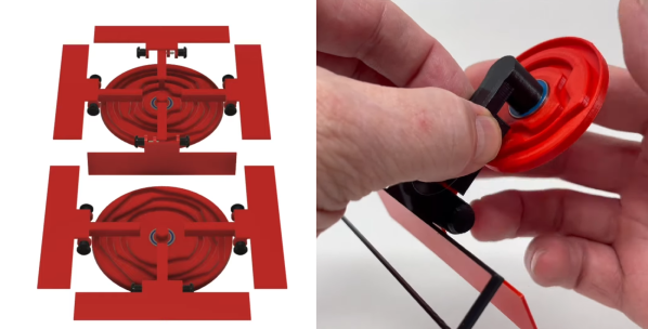
Seven-segment displays have been around for a long time, and there is a seemingly endless number of ways to build them. The latest of is a mechanical seven-segment from a master of 3D printed mechanisms, [gzumwalt], and can use a single motor to cycle through all ten possible numbers.

The trick lies in a synchronized pair of rotating discs, one for the top four segments and another for the bottom three segments. Each disc has a series of concentric cam slots to drive followers that flip the red segments in and out of view. The display can cycle through all ten states in a single rotation of the discs, so the cam paths are divided in 36° increments. [gzumwalt] has shown us a completed physical version, but judging by CAD design and working prototype of a single segment, we are pretty confident it will. While it’s not shown in the design, we suspect it will be driven by a stepper motors and synchronized with a belt or intermediate gear.

Another 3D printed mechanical display we’ve seen recently is a DIY flip dot, array, which uses the same electromagnet system as the commercial versions. [gzumwalt] has a gift for designing fascinating mechanical automatons around a single motor, including an edge avoiding robot and a magnetic fridge crawler.

Continue reading “Mechanical 7-Segment Display Uses A Single Motor”

Raspberry Pi Pico Oscilloscope

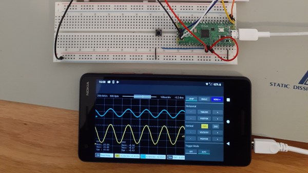
As you dive deeper into the world of electronics, a good oscilloscope quickly is an indispensable tool. However, for many use cases where you’re debugging low voltage, low speed circuits, that expensive oscilloscope is using only a fraction of its capabilities. As a minimalist alternative for these use cases [fhdm-dev] created Scoppy, a combination of firmware for the Raspberry Pi Pico and an Android app to create a functional oscilloscope.

As you would expect, the specifications are rather limited, capturing a maximum of 100 kpts at a speed of 500 kS/s shared between the two channels. Without some additional front end circuitry to protect the Pico, the input voltage is limited to 0-3.3 V. Neither the app nor the firmware is open source, and getting access to the second channel and removing ads requires a ~$3 in-app purchase. Even so, we can still think of plenty of practical uses for a ~$7 oscilloscope. If you do decide to add some front-end circuitry to change to voltage range, you can set them in the app, and switch between them by pulling certain GPIO pins high or low. The app has most of the basic oscilloscope features covered, continuous and single shot capture, adjustable trigger settings and a scalable waveform display.

Simple, cheap oscilloscopes like these have their place, but you start to understand why the “real” ones are so expensive when you see what goes into developing a high performance oscilloscope.

Some Of The Many Ways To Build AM Transmitters And Receivers

AM radios are relatively simple devices, and building one is a good way to start exploring the world of radio communications. [GreatScott] does exactly this in the video after the break, building both a transmitter and receiver.

At the most basic level, AM radio works by generating a carrier wave with an oscillator, and then modulating the amplitude with an audio signal. Around these parts, the venerable 555 timer is always brought up whenever things get to oscillating; so you’ll no doubt be happy to see [GreatScott] decided to give it a shot for his first experiments, testing two popular 555 transmitter circuits. One uses the control voltage pin to input the audio signal, while the other uses the reset pin. The CV-pin version worked slightly better, but it was still just barely possible to distinguish a voice over a standard commercial AM/FM receiver.

The next attempt was with a XR2206 function generator kit, which worked quite well when combined with a simple microphone amplifier circuit. But this time the receiving side was swapped out, as [GreatScott] built a basic circuit around a TA7642 AM amplifier/demodulator IC, with only six passive components and a hand-wound coil.

There is no shortage of ways to build AM radios, and we’ve covered quite a few over the years. Off course a 555 timer can also be used in a receiver, and building transmitters using only discrete components is quite simple, as demonstrated by the 10-minute transmitter and single transistor transmitter.

Continue reading “Some Of The Many Ways To Build AM Transmitters And Receivers”

Fat Tire Bike Turned Hubless

Bicycle wheels have looked pretty much the same for over a century, and for very good reason: It works. [The Q] decided to ignore reason for a bit and focus on looks, so he built a fat tire bike without any hubs or spokes.

To make this work, he fabricated two sets of ring shaped “hubs” about the size of the rims, with a series of ball bearings around the circumference for the rims to roll around. The original forks were cut short and welded to a set of brackets that bolt to new hubs. This further complicates the back end as there’s nowhere to attach the sprocket cassette. The original rear hub, cassette and disc brake was moved to the inside of the frame. This drives the rear wheel using a second chain attached to a large ring sprocket mounted directly on the rim. The front brake was simply eliminated.

While this new design won’t be taking on existing bicycles, we doubt practicality was a priority in the build. It’s definitely a head turner, and we can’t help but see an opportunity to go even further and build a TRON bicycle.

Just recently, [The Q] turned another fat tire bike into an all-wheel-drive extreme off-roader. For another pedal-powered head turner, check out the strandbeest bicycle.

Mechanically Multiplexed Flip-Dot

Flip dots displays are timeless classics, but driving the large ones can quickly turn into a major challenge. The electromagnets require a lot of current to operate, and the driver circuits can get quite expensive. [James Bruton] wanted to build his own, but followed a bit of a different route, building a mechanically multiplexed flip dot (ball?) display.

Each of the dots on [James]’ 5×3 proof of concept is a bistable mechanical mechanism that can either show or hide a ping pong ball sized half sphere. Instead of using electromagnets, the dots are flipped by a row of micro servos mounted on a moving carriage behind the display. The mechanism is derived from one of [James]’ previous projects, a mechanical multiplexer. Each dot mechanism has a hook at the back of the mechanism for a servo to push or pull to flip the dot. A major disadvantage of this design is the fact that the servo horn must match the state of the dot before moving through the hook, otherwise it can crash and break something, which also reduces the speed at which the carriage can move.

This build was just to get a feel for the concept, and [James] already has several ideas for changes and improvements. The hook design can certainly change, and a belt drive would really speed things up. We think this mechanical display is a very interesting design challenge, and we are interested to hear how our readers would tackle it? Let us know in the comments below.

Recently we covered a 3D printed flip dot display for the first time. It’s still small and [Larry Builds] is working out the kinks, but we would love to see it eventually match the mesmerising effect of Breakfast’s large installations.

Bungee And Cam Assisted Actuator For OpenDog

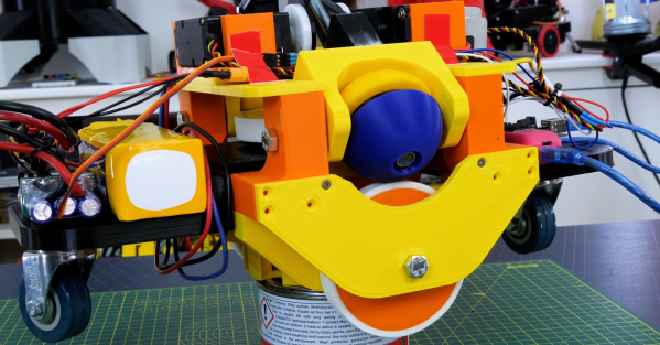
One of the challenges of many walking robot designs is the fact that they draw current just to stay upright. This was exactly the case for one [James Bruton]’s quadruped robots, where the knee motors were getting too hot to touch. Adding springs to take some of the load is not as simple it might seem, so [James] created a bungee assisted cam mechanism to do the job.

For a normal spring-loaded lever, force is proportional to how much the spring is stretched, which will require the actuators to draw more and more current as it lifts the leg higher. For the spring force to remain constant throughout the range of motion, the length of the lever arm must become continuously shorter as the knee is bent.  [James] did this by stretching a bungee cord around a cam. The added bulk of the cam does however cause the knees to knock into each other in some scenarios, but [James] plans to adjust the robot’s gait to avoid this. He didn’t get around to actually measuring the current draw reduction, but the motor temperature has dropped significantly, only being slightly warm after a test run.

These tests were done with OpenDog V2, but [James] is already working on the design of V3, which will use 3D printed cycloidal gearboxes. At the moment, that build is still being delayed thanks to the global component shortage. Continue reading “Bungee And Cam Assisted Actuator For OpenDog”