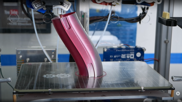
[Stefan] from CNCKitchen wanted to make some bendy tubes for a window-mountable ball run, and rather than coming up with some bent tube models, it seemed there might be a different way to achieve the desired outcome. Starting with a simple tube model designed to be quickly printed in vase mode, he wrote a Python script which read in the G-Code, and modified it allow it to be bent along a spline path.
Vase mode works by slowly ramping up the Z-axis as the extruder follows the object outline, but the slicing process is still essentially the same, with the object sliced in a plane parallel to the bed. Whilst this non-planar method moves the Z-axis in sync with the horizontal motion (although currently limited to only one plane of distortion, which simplifies the maths a bit) it is we guess still technically a planar solution, but just an inclined plane. But we digress, non-planar in this context merely means not parallel to the bed, and we’ll roll with that.
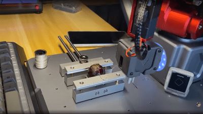
[Stefan] explains that there are quite a few difficulties with this approach. The first issue is that on the inside of the bend, the material flow rate needed to be scaled back to compensate. But the main problem stems from the design of the extruder itself. Intended for operating parallel to the bed, there are often a few structures in the way of operating at an angle, such as fan mounts, and the hotend itself. By selecting an appropriate machine and tweaking it a bit, [Stefan] managed to get it to work at angles up to 30 degrees off the horizontal plane. One annoyance was that the stock nozzle shape of his E3D Volcano hotend didn’t lend itself to operating at such an inclination, so he needed to mount an older V6-style tip with an adapter. After a lot of tuning and fails, it did work and the final goal was achieved! If you want to try this for yourselves, the code for this can be found on the project GitHub.
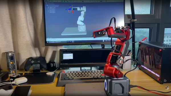
If you want to learn more about non-planar printing, we’ve covered the process of non-planar slicing a while back, and if you think your 2.5D printer doesn’t quite have the range for really funky print paths, then you may want to look into a robot arm based printer instead.
Continue reading “Bend Your Vase Mode Prints By Hacking The GCode”