Building A 3D Printed Scanning Tunneling Microscope

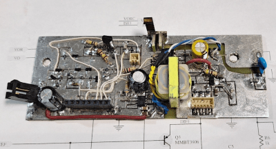
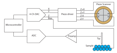
YouTuber [MechnicalRedPanda] has recreated a DIY STM hack we covered about ten years ago, updating it to be primarily 3D-printed, using modern electronics, making it much more accessible to many folks. This simple STM setup utilises a piezoelectric actuator constructed by deliberately cutting a piezo speaker into four quadrants. With individual drive wires attached to the four quadrants. [MechPanda] (re)discovered that piezoelectric ceramic materials are not big fans of soldering heat. Still, in the absence of ultrasonic welding equipment, he did manage to get some wires to take to the surface using low-temperature solder paste.

As you can tell, you can only image conductive samples

A makeshift probe holder was glued on the rear side of the speaker actuator, which was intended to take a super sharp needle-like piece of tungsten wire. Putting the wire in tension and cutting at a sharp angle makes it possible with many attempts to get some usable points. Usable, in this instance, means sharp down the atomic level. The sample platform, actuator mount and all the connecting parts are 3D-printed with PA-CF. This is necessary to achieve enough mechanical stability with normal room temperature fluctuations. Three precision screws are used to level the two platforms in a typical kinematic mount structure, which looks like the only hard-to-source component. A geared stepper motor attached to the probe platform is set up to allow the probe to be carefully advanced towards the sample surface. Continue reading “Building A 3D Printed Scanning Tunneling Microscope”

Making A Split-Anode Magnetron

YouTuber The Science Furry has been attempting to make a split-anode magnetron and, after earlier failures, is having another crack at it. This also failed, but they’ve learned where to focus their efforts for the future, and it sure is fun to follow along.

The magnetron theory is simple enough, and we’ve covered this many times, but the split anode arrangement differs slightly from the microwave in your kitchen. The idea is to make a heated filament the cathode, so electrons are ejected from the hot surface by thermionic emission. These are forced into a spiral path using a perpendicular magnetic field. This is a result of the Lorentz force. A simple pair of magnets external to the tube is all that is needed for that. Depending on the diameter of the cavity and the gap width, a standing wave will be emitted. The anodes must be supplied with an alternating potential for this arrangement to work. This causes the electrons to ‘bunch up’ as they cross the gaps, producing the required RF oscillation. The split electrodes also allow an inductor to be added to tune the frequency of this standing wave. That is what makes this special.

Fizz, pop, ah well.

The construction starts with pre-made end seals with the tungsten wire electrode wire passing through. In the first video, they attempted to coat the cathode with barium nitrate, but this flaked off, ruining the tube. The second attempt replaces the coiled filament with a straight wire and uses a coating paste made from Barium Carbonate mixed with nitrocellulose in a bit of acetone. When heated, the nitrocellulose and the carbonate will decompose, hopefully leaving the barium coating intact. After inserting the electrode assembly into a section of a test tube and welding on the ends, the vacuum could be pulled and sealed off. After preheating the cathode, some gasses will be emitted into the vacuum, which is then adsorbed into a nearby titanium wire getter. At least, that’s the theory.

Upon testing, this second version burned out early on for an unknown reason, so they tried again, this time with an uncoated cathode. Measuring the emission current showed only 50 uA, which is nowhere near enough, and making the filament this hot caused it to boil off and coat the tube! They decide that perhaps this is one step too many and need to experiment with the barium coating by making simpler diode tubes to get the hang of the process!

If this stuff is over your head, you need a quick history lesson about the magnetron. Next check out this teardown. Finally, we have covered DIY magnetrons before, like this excellent DIY magnetron-powered plasma sputtering device. Yes, you read that correctly.

Continue reading “Making A Split-Anode Magnetron”

The Statial-b Open Source Adjustable Mouse

Many of us are very heavy computer users, and two items that can affect our comfort and, by extension, our health are the keyboard and the mouse. We’ve covered many ergonomic and customisable keyboards over the years, but we are not sure we’ve covered a fully adjustable mouse until now. Here’s [Charlie Pyott] with their second take on an adjustable mouse, the open source, statial-b.

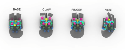
[Charlie] goes into an extensive discussion of the design process in the video after the break, which is a fascinating glimpse into the methods used by a professional industrial designer. The statial concept breaks the contact surfaces of the mouse into fixed and moveable sections. The moveable sections are attached to the mouse core via a pair of ball joints connected with extendible arms, allowing the surfaces to be adjusted for both position and orientation. The design process starts with 3D scanning their ‘workhorse mouse,’ a Razer Deathadder Elite. This creates a reference volume within which the statial body should fit in its minimal configuration.

So which mouse grip style are you into?

The design has a fixed central core, with each button (including the central scroller) separately adjustable. The side panel with a pair of thumb buttons is also moveable. Creating a model in Rhino 3D working with the grasshopper visual programming environment [Charlies] explored the surface constraints for the base, claw, finger and vertical grip styles common among mouse users. This model was then fed into Fusion 360 for the detailed design. After completing the design, it was passed back into Rhino 3D to add lattice effects to the panel. This helps reduce weight and lets the internal LEDs shine through. The design is intended for resin printing, so you could go wild with the visuals by missing custom resins if you were so inclined.

Continue reading “The Statial-b Open Source Adjustable Mouse”

A DaVinci Screw-Cutting Machine

It’s not news that Leonardo DaVinci was somewhat ahead of his time, and over the centuries many of the creations in his sketchbooks have been created and proved quite functional. The guys from the YouTube channel How To Make Everything have been looking at one such sketch, a screw thread-cutting machine. At first glance, it seems a little flawed. Threads are hard to make by hand, and you can see that this thread-cutting machine needs two identical threads operating as a reference to make it work. However, as the guys demonstrate, you can create threads by hand using simple methods.

Starting with an offset blade mounted on a block with a hole through it, a dowel can be scribed with a starter thread. This can then be worked by hand to cut enough of a groove for the application. They demonstrated that the machine was viable using nothing but wood for construction. A metal blade was mounted, and some preload force was applied to it with a spring. The dowel to be cut was loaded, and the machine ran back and forth enough times to create a very nice-looking screw thread. And once you’ve made two identical threaded dowels, you can use them to upgrade the machine or even build a second. Once you have a repeatable way to make such threads, all kinds of applications become more accessible. Need a bench vice? No problem now!

Whilst the demonstration doesn’t precisely follow the plans laid out by the master inventor, they aren’t all that clear on the cutting tool after all, it’s nice to see people still wanting to build his ideas, and we’ll certainly be following along.

If you like these “from scratch” builds, you’ll like this other one. Leonardo’s work wasn’t just about machines; he was also very interested in science. Here’s a recreation of his demonstration of gravity as a form of acceleration.

Continue reading “A DaVinci Screw-Cutting Machine”

Learn GPU Programming With Simple Puzzles

Have you wanted to get into GPU programming with CUDA but found the usual textbooks and guides a bit too intense? Well, help is at hand in the form of a series of increasingly difficult programming ‘puzzles’ created by [Sasha Rush]. The first part of the simplification is to utilise the excellent NUMBA python JIT compiler to allow easy-to-understand code to be deployed as GPU machine code. Working on these puzzles is even easier if you use this linked Google Colab as your programming environment, launching you straight into a Jupyter notebook with the puzzles laid out. You can use your own GPU if you have one, but that’s not detailed.

The puzzles start, assuming you know nothing at all about GPU programming, which is totally the case for some of us! What’s really nice is the way the result of the program operation is displayed, showing graphically how data are read and written to the input and output arrays you’re working with. Each essential concept for CUDA programming is identified one at a time with a real programming example, making it a breeze to follow along. Just make sure you don’t watch the video below all the way through the first time, as in it [Sasha] explains all the solutions!

Confused about why you’d want to do this? Then perhaps check out our guide to CUDA first. We know what you’re thinking: how do we use non-nVIDIA hardware? Well, there’s SCALE for that! Finally, once you understand CUDA, why not have a play with WebGPU?

Continue reading “Learn GPU Programming With Simple Puzzles”

3D Printing On Top Of Laser Cut Acrylic

[Julius Curt] needed to mark acrylic panels with a bit more clarity than the usual way of rastering the surface, so they attempted to 3D print directly to an acrylic sheet, which worked perfectly. The obvious way to do this was to bond the acrylic sheet to the bed with glue temporarily, but another way was tried, and it’s much less messy and precarious.

The bond between a 3D print and acrylic is very strong

The first step was to create a 3D model which combined a constraining ‘fence’ to contain the acrylic panel with the required artwork floating above. It was easy enough to run the print long enough to build the fence, then pause the print mid-way to add the pristine panel and restart after a quick re-prime and wipe.

There were a few simple takeaways from the video below. First, to ensure sufficient tolerance between the fence and the panel, consider the layer width (plus associated tolerance when printed) and the laser kerf of your machines to ensure a not-too-sloppy fit. Secondly, that hot nozzle won’t do the acrylic surface any favours during travel moves, so enabling Z-hopping is essential!

Another use for this simple technique is to fully incorporate an acrylic sheet within a print by pausing at an appropriate height again, dropping the panel in, and continuing the print. A degree of overlap will lock the panel tight, with the plastic bonding very firmly to the acrylic, as [Julius] demonstrates in the video.

It’s always a delight to see how techniques can combine to create the desired effects. Here’s how to use a color laser printer and toner transfer paper to apply designs to a 3D printing front panel. Whilst we’re thinking about the multitude of uses for hacking with acrylic, what about not doing that and using corrugated plastic instead?

Continue reading “3D Printing On Top Of Laser Cut Acrylic”

Revisiting 1990’s Mac Games That Never Were

[John Calhoun] was digging around their old MAC hard drives, revisiting some abandoned shareware games they wrote over three decades ago, and has uploaded the recovered disk images to GitHub for everyone to take apart and play with. This repository has a few of the games complete with their development files and the compiler environment, a mixture of Think Pascal and C.

Back then, [John] had a solid mantra when creating projects, specifically prototyping fast and abandoning things quickly if they were not working out. The blog shows a list of twenty-eight projects, of which only five ever made it to release, with all the rest left to rot. This is reminiscent of the attitude around Silicon Valley of moving fast and breaking things. Anyway, reasons for ditching a project ranged from ‘too much sprite work’ for a D’n’D style game to simply ‘not fun’ for some with clunky control mechanisms. [John] even abandoned a neat-looking steampunk flight simulator due to the sheer amount of work needed. Of course, it’s not all lost effort. Much of the code written was reused across multiple projects; after all, there’s no point in re-writing a cosine lookup table if you’ve already got one kicking around in another project.

Still, it’s a fun trip down memory lane, looking deep into projects that never were and the development journey to becoming a successful programmer.

While it isn’t hard to find old Macintosh hardware, some are not in great shape. Here’s a fun Hackintosh project that uses retro parts. [John] was featured a while back, with his homage to his first mac, a sleek Rpi-powered eInk desk ornament. Finally, we can’t talk about recovering retro software without looking in detail at the floppy disk themselves.