Where the Hackaday Cat goes when she steps over the threshold into the wider world is a mystery, she reveals her whereabouts strictly on her terms and would we suspect be very cagey were we able to ask her about it. [Andy C] however has a need to know where his cat is spending her time, so he’s made a GPS collar for a bit of feline spying.
There are commercial GPS collars for pets, but they all share the flaw of extremely limited battery life. His challenge then was to create a collar that delivered the required pinpoint fix alongside a battery life measured in months. The solution was a combination of a low-power miniature GPS receiver and a low-power PC microcontroller hooked up to an FSK radio whose frequency he doesn’t give but which we suspect is probably the usual 433 MHz. The collar remains in low power mode until it receives a call on the FSK, at which point it wakes up, gets a GPS fix, transmits it, and returns to sleep.
The summary links to a series of posts which provide an extremely detailed look at all aspects of the project, and go well beyond mere GPS trackers for a cat. If you have an interest in low power devices or antenna matching for example, you’ll find a lot of interesting stuff in these pages. Of course, if all you need is a GPS tracker though, you may prefer a simpler option.
As is always the case with a significant hacker camp, we’ve been awaiting the official badge announcement for the upcoming Electromagnetic Field 2018 hacker camp with huge interest. These badges, for readers who may have been on Mars for the past few years, are part of a lively scene of wearable electronics at hacker conferences and camps, and can usually be expected to sport a fully-fledged computer in their own right along with other special functionality.
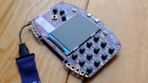
The announcement of the 2018 badge, dubbed the TiLDA Mk4, does not disappoint. We’d been told that there would be an on-site GSM network for which the welcome packs would contain a SIM, and the well-prepared among us had accordingly dusted off our old Nokia handsets alongside our DECT phones. What we hadn’t expected was that the SIM would be for the badge, because the Mk4 is a fully-fledged hackable mobile phone in its own right. The network will be fully functional for calls and texts within the camp, though since it does not explicitly say so we expect that external calls may be an impossibility. Afterwards though it will remain a usable device on any GSM network, giving it a lease of post-camp life that may see more of them staying in use rather than joining the hacker’s dusty collection in a drawer.
Beyond the party-piece phone it appears to follow the lead of its 2016 predecessor, with the same Python environment atop a TI chipset including an MSP432E4 ARM Cortex M4F microcontroller running at 120MHz with 256kB of internal and 8MB of external RAM, a CC3210 WiFi processor, and the usual battery of sensors, LEDs and GPIOs. Importantly, it also has a Shitty Add-on connector. The 2016 badge was remarkably easy to develop for, and we expect that there will soon be an impressive array of apps for this badge too. If any reader would like to put together a Hackaday feed reader app, we can’t offer you fortune but fame such as we can bestow awaits.
We’ll bring you more information as we have it about the TiLDA Mk4, as well as a hands-on report when one lands in front of us. Meanwhile you’d like to see a retrospective of past EMF badges as a demonstration of where this one has come from, have a read of our coverage of the 2016 and 2014 badges.
If you move among artists, you may have encountered a few printmakers. They create a drawing by cutting through a wax layer that has been deposited on a sheet of copper, then etching the plate and removing the wax. Ink is then rolled onto the plate and cleaned from the flat surface, remaining in the cracks created by the etching. A print is made by putting inked plate and a sheet of paper through a roller press at significant pressure, squeezing the ink from the cracks onto the paper. The result is a beautiful print, but the press required to do the job is by no means cheap.
[Martin Schneider] has addressed this expense with his Open Press project, by producing a printmaking press that can be 3D-printed for a fraction of the outlay of a traditional press. It’s by no means a large model, but appears no less functional for it.
The form of the press is straightforward enough, with a print bed that is drawn between a pair of rollers by a rack-and-pinion gear, and as you would imagine the construction is quite substantial. It’s all CC licensed, and you can make one for yourself if you would like, by downloading the files from Thingiverse.
It’s fair to say that printmaking hasn’t appeared much here, but we can see this press could have significant use beyond artistic applications. Meanwhile it’s a great example of 3D printing providing the means to reduce the barrier to entry for something that was previously quite an expensive pursuit.
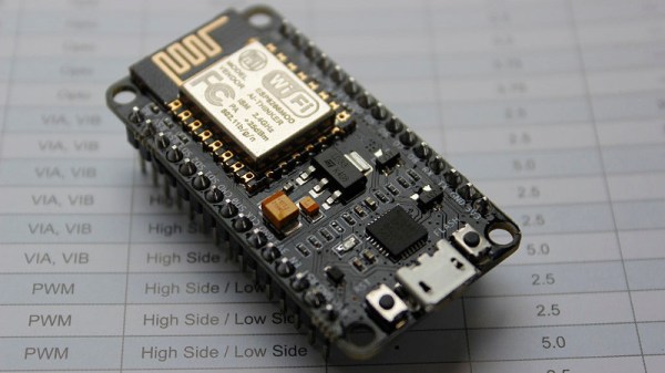
If your interest has been piqued by the inexpensive wireless-enabled goodness of the ESP8266 microcontroller, but you have been intimidated by the slightly Wild-West nature of the ecosystem that surrounds it, help is at hand. [Alexander] is creating a series of ESP8266 tutorials designed to demystify the component and lead even the most timid would-be developer to a successful first piece of code.
If you cast your mind back to 2014 when the ESP8266 first emerged, it caused great excitement but had almost no information surrounding it. You could buy it on a selection of modules, but there were no English instructions and no tools to speak of. A community of software and hardware hackers set to work, resulting in a variety of routes into development including the required add-ons to use the ever-popular Arduino framework. Four years later we have a mature and reliable platform, with a selection of higher-quality and well supported boards to choose from alongside that original selection.
The tutorials cover the Arduino and the ESP, as well as Lua and the official SDK. They are written for a complete newcomer, but the style is accessible enough that anyone requiring a quick intro to each platform should be able to gain something.
Our community never ceases to amaze us with the quality of the work that emerges from it. We’ve seen plenty of very high quality projects over the years, and it’s especially pleasing to see someone such as [Alexander] giving something back in this way. We look forward to future installments in this series, and you should keep an eye out for them.
Infra-red remote control is something of a Done Deal when it comes to hardware hacking, it has been comprehensively reverse engineered, and there exist libraries and software packages to seamlessly take care of all its quirks. Just occasionally though, along comes an IR remote whose protocol doesn’t follow that well-worn path
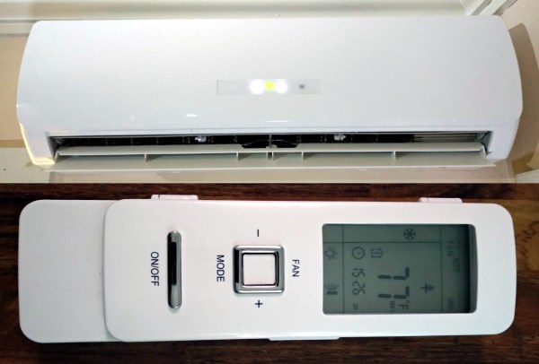
[William Dudley] found himself in this position with an air-conditioning unit remote control. He found it sent a stream of data with all settings of the machine rather than the single command codes you might expect from a familiar TV remote. The solution was to reverse engineer and reimplement the IR codes.
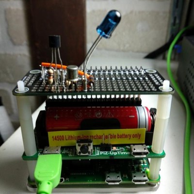
His reverse engineering relied on an Arduino and IR receiver which he used to sniff the packets coming out of the remote. Eventually he was able to recognise some of the functions from the remote, and create his own protocol that can recreate most of the remote’s functions. This was pushed over to a Raspberry Pi Zero which uses an IR LED to command the air conditioner, joining the ranks of his growing home automation setup.
The write-up makes for a fascinating primer on analysis of obscure IR protocols, and is well worth a read for anybody with an interest in the topic. Meanwhile if you want more IR reverse engineering stories, try this tale of a bathroom scale.
Remember a the time before oscilloscopes had a brain? It’s easy to forget as we’ve become accustomed to a class of simple solid state oscilloscope using a microcontroller as signal processor and a small LCD display to show the resulting waveforms. They are commonly available as inexpensive kits, and while their bandwidth is not huge they give a good account of themselves in low frequency applications. But of course, originally the signal processing was handled in a much simpler way.
[SimpleTronic] reminds us that a small solid state oscilloscope does not need a microcontroller, with a ‘scope on a breadboard that displays waveforms on an LED matrix in a much more traditional manner. This is very much an analogue oscilloscope, in which the X deflection circuitry of the CRT is replaced by a decade counter stepping through the columns of LEDs on the display, and the Y deflection circuitry by some analogue signal conditioning followed by an LM3914 bar graph display chip driving the display rows. There are a few refinements such as a trigger circuit, but it remains a very understandable and surprisingly simple device.
It has a claimed bandwidth of 40 kHz defined by its sweep ranges rather than its analogue bandwidth, and an input voltage range from 50 mVpp to 50 Vpp. It’s hardly a useful instrument due to its low bandwidth, but its strength lies in novelty and in understanding a traditional oscilloscope rather than in its utility. You can see it in action in the video we’ve placed below the break.
‘Scopes of limited use appear from time to time on these pages. A favourite of ours is this soldering iron.
A couple of weekends ago on a farm in rural England with a cider orchard and a very good line in free-range pork sausages, there was the first get-together of the nascent British Hacky Racers series of competitions for comedic small electric vehicles. At the event, [Mark Mellors] shot a set of video interviews with each of the attendees asking them to describe their vehicles in detail, and we’d like to present the first of them here.
The Selby is unique among all the Hacky Racers in being a six-wheeler. It’s the creation of [Michael West] of MK Makerspace, and it bears a curious resemblance to a pair of PowaKaddy golf buggies grafted together. The resulting vehicle has four driven wheels and two steering wheels, and though it is hardly a speedy machine this extra drive gives it what is probably the most hefty pulling power of all the contestants. In the video below it appears without bodywork, but we are told that something impressive will sit upon it when it appears at Electromagnetic Field.
View of motors fed with 24 V driving the rear wheels
I should own up, that the Selby is a familiar to Hackaday, as I’m also an MK Makerspace member. I’ve seen it progress from two worn-out golf trolleys to its current state, and seen first hand some of the engineering challenges that has presented. The PowaKaddy buggies of that vintage are extremely well-engineered, with a Curtis controller that is still comfortably within spec even when driving four motors instead of two. Unusually for a Hacky Racer the power comes from a pair of huge lead-acid batteries, as these were the power source supplied with the PowaKaddy from new and it made little sense to change them. Gearing is fixed at golf-course speeds, and braking comes from a pair of brakes fitted on the motors. The motors themselves are simple DC affairs, with significant weatherproofing.
Cutting and shutting the two PowaKaddys was straightforward enough, but introduced a warp to the chassis that was solved by your Hackaday scribe hanging on the end of a lever formed from a long piece of 4-by-2 while [Mike] and friends stood on the other end of the Selby.
As a driving experience it’s exciting enough but lacks the speed of some of its competitors. Where it really comes into its own though is off-road, as the multi-wheel drive and broad treaded tyres power it across mud and offer powersliding opportunities on wet grass.