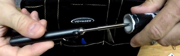
Reverse Polish Notation And Its Mildly Confusing Elegance

The best rummage sale purchase I ever made was a piece of hardware that used Reverse Polish Notation. I know what you’re thinking… RPN sounds like a sales gimmick and I got taken for a fool. But I assure you it’s not only real, but a true gem in the evolution of computing.

Best rummage sale find ever!

Sometime in the 1980s when I was a spotty teen, I picked up a calculator at a rummage sale. Protected by a smart plastic case, it was a pretty good condition Sinclair Scientific that turned out when I got it home to have 1975 date codes on its chips, and since anything with a Sinclair badge was worth having it became mine for a trifling amount of money. It had a set of corroded batteries that had damaged one of its terminals, but with the application of a bit of copper strip I had a working calculator.

And what a calculator! It didn’t have many buttons at a time when you judged how cool a scientific calculator was by the prolific nature of its keyboard. This one looked more akin to a run-of-the-mill arithmetic calculator, but had button modes for trigonometric functions and oddly an enter key rather than an equals sign. The handy sticker inside the case explained the mystery, this machine used so-called Reverse Polish Notation, or RPN. It spent several years on my bench before being reverently placed in a storage box of Sinclair curios which I’ve spent half a day turning the house over to find as I write this article.

Continue reading “Reverse Polish Notation And Its Mildly Confusing Elegance”

One Chip, Sixteen Times The RAM

Have you ever upgraded your computer’s memory sixteen-fold, with a single chip? Tynemouth Software did for a classic Sinclair micro.

For owners of home computers in the early 1980s, one of the most important selling points was how much RAM their device would have. Sometimes though there just wasn’t much choice but to live with what you could afford, so buyers of Sinclair’s budget ZX81 computer had to put up with only 1 kiB of memory. The system bytes took up (by this writer’s memory) around 300 bytes, so user programs were left with only around 700 bytes for their BASIC code. They were aided by Sinclair’s BASIC keywords stored as single bytes, but still that was a limit that imposed coding economy over verbosity.

Sinclair sold a 16 kiB upgrade, the so-called “Rampack”, which located on the ’81’s edge connector and was notorious for being susceptible to the slightest vibration. Meanwhile the mainboard had provision for a 2 kiB chip as a drop-in that was never sold in the UK, and enterprising users could fit larger capacities with soldered combinations of other chips piggybacking the original. And this is what the Tynemouth people have done, they’ve replaced their machine’s dual 1 kiB x 4 chips with a single 62256, and with a bit of pin-bending they’ve managed to do it without the track-cutting that normally accompanies this mod.

Adding chips to a 36-year-old home computer for which there are plenty of available Rampacks might seem a bit of a niche, but in doing so they’ve made a standalone ’81 that’s just a little bit more useable. They’ve also brought a few other components up-to-date, with a composite video mod, switching regulator, and heatsink for the rare ULA chip. If you are of a Certain Generation, it might just bring a tear to your eye to see a ZX81 being given some love.

Did you lose your ZX81 along the way? How about emulating one in mbed?

FoTW: LED Strips Make Awful Servo Drivers

We must all have at some time or another spotted a hack that seems like an incredible idea and which just has to be tried, but turns out to have been stretching the bounds of what is possible just a little too far. A chunk of our time has disappeared without trace, and we sheepishly end up buying the proper part for the job in hand.

[Orionrobots] had a conversation with a YouTube follower about LED strips. An LED strip contains a length of ready-made PWM drivers, they mused. Wouldn’t it be great then, if each of the drivers on a strip could be connected to a servo, making the strip a ready-made single-stop SPI servo driver. With a large multi-servo robot to build, he set to work on a strip of WS2801s.

If you are in the Soldering Zone and have elite skills at the iron, then soldering a wire to a surface mount driver chip is something entirely possible. For mere mortals though it’s a bit of a challenge, and he notes just how much extra time it’s added to the project. The fun starts though when the servo is hooked up, the best that can be said is that it vibrates a bit. On paper, the LED drivers should be able to drive a servo, because they can create the correct waveform. But in practice the servo is designed to accept a logic level input while the driver is designed to sit in series with an LED and control its current. In practice therefore the voltages required for a logic transition can’t quite be achieved.

He concludes by recommending that viewers splash out on a servo driver board rather than trying an LED strip. We applaud him for the effort, after all it’s a hack any of us might have thought of trying for ourselves.

Continue reading “FoTW: LED Strips Make Awful Servo Drivers”

Hackaday Prize Entry: Unlock Your PC The RFID Way

Sometimes we see projects whose name describes very well what is being achieved, without conveying the extra useful dimension they also deliver. So it is with [Prasanth KS]’s Windows PC Lock/Unlock Using RFID. On the face of it this is a project for unlocking a Windows PC, but when you sit down and read through it you discover a rather useful primer for complete RFID newbies on how to put together an RFID project. Even the target doesn’t do it justice, there is no reason why this couldn’t be used with any other of the popular PC operating systems besides Windows.

The project takes an MRFC-522 RFID module and explains how to interface it to an Arduino. In this case the Arduino in question is an Arduino Pro Micro chosen for its ability to be a USB host. The supplied code behaves as a keyboard, sending the keystroke sequence to the computer required to unlock it. The whole is mounted in what seems to be a 3D printed enclosure, and for ease of use the guts of the RFID tag have been mounted in a ring.

As we said above though, the point of this project stretches beyond a mere PC unlocker. Any straightforward RFID task could use this as a basis, and if USB is not a requirement then it could easily use a more run-of-the-mill Arduino. If you’re an RFID newbie, give it a read.

Plenty of RFID projects have made it here before, such as this door lock. And we’ve had another tag in a ring, too.

Retrotechtacular: Weather Station Kurt

Sometimes when researching one Hackaday story we as writers stumble upon the one train of thought that leads to another. So it was with a recent look at an unmanned weather station buoy from the 1960s, which took us on a link to a much earlier automated weather station.

The restored Kurt in the Canadian National War Museum.

Weather Station Kurt was the only successful installation among a bold attempt by the German military during the Second World War to gain automated real-time meteorological data from the Western side of the Atlantic. Behind that simple sentence hides an extremely impressive technical and military achievement for its day. This was the only land-based armed incursion onto the North American continent by the German military during the entire war. Surrounded as it was though by secrecy, and taking place without conflict in an extremely remote part of Northern Labrador, it passed unnoticed by the Canadian authorities and was soon forgotten as an unimportant footnote in the wider conflagration.

Kurt took the form of a series of canisters containing a large quantity of nickel-cadmium batteries, meteorological instruments, a telemetry system, and a 150W high frequency transmitter. In addition there was a mast carrying wind speed and direction instruments, and the transmitting antenna. In use it was to have provided vital advance warning of weather fronts from the Western Atlantic as they proceeded towards the European theatre of war, the establishment of a manned station on enemy territory being too hazardous.

A small number of these automated weather stations were constructed by Siemens in 1943, and it was one of them which was dispatched in the U-boat U537 for installation on the remote Atlantic coast of what is now part of modern-day Canada. In late October 1943 they succeeded in that task after a hazardous trans-Atlantic voyage, leaving the station bearing the markings of the non-existent “Canadian Meteor Service” in an attempt to deceive anybody who might chance upon it. In the event it was not until 1977 that it was spotted by a geologist, and in 1981 it was retrieved and taken to the Canadian War Museum.

There is frustratingly little information to be found on the exact workings on the telemetry system, save that it made a transmission every few hours on 3940kHz. A Google Books result mentions that the transmission was encoded in Morse code using the enigmatic Graw’s Diaphragm, a “sophisticated contact drum” named after a Dr. [Graw], from Berlin. It’s a forgotten piece of technology that defies our Google-fu in 2017, but it must in effect have been something of a mechanical analogue-to-digital converter.

Should you happen to be visiting the Canadian capital, you can see Kurt on display in the Canadian War Museum. It appears to have been extensively restored from the rusty state it appears in the photograph taken during its retrieval, it would be interesting to know whether anything remains of the Graw’s Diaphragm. Do any readers know how this part of the station worked? Please let us know in the comments.

Weather station Kurt retrieval image, Canadian National Archives. (Public domain).

Weather station Kurt in museum image, SimonP (Public domain).

Aussies Propose Crackdown On Insecure IoT Devices

We’ve all seen the stories about IoT devices with laughably poor security. Both within our community as fresh vulnerabilities are exposed and ridiculed, and more recently in the wider world as stories of easily compromised baby monitors have surfaced in mass media outlets. It’s a problem with its roots in IoT device manufacturers treating their products as appliances rather than software, and in a drive to produce them at the lowest possible price.

The Australian government have announced that IoT security is now firmly in their sights, announcing a possible certification scheme with a logo that manufacturers would be able to use if their products meet a set of requirements. Such basic security features as changeable, non-guessable, and non-default passwords are being mentioned, though we’re guessing that would also include a requirement not to expose ports to the wider Internet. Most importantly it is said to include a requirement for software updates to fix known vulnerabilities. It is reported that they are also in talks with other countries to harmonize some of these standards internationally.

It is difficult to see how any government could enforce such a scheme by technical means such as disallowing Internet connection to non-compliant devices, and if that was what was being proposed it would certainly cause us some significant worry. Therefore it’s likely that this will be a consumer certification scheme similar to for example the safety standards for toys, administered as devices are imported and through enforcement of trading standards legislation. The tone in which it’s being sold to the public is one of “Think of the children” in terms of compromised baby monitors, but as long-time followers of Hackaday will know, that’s only a small part of the wider problem.

Thanks [Bill Smith] for the tip.

Baby monitor picture: Binatoneglobal [CC BY-SA 3.0].

Why Not Expose Your PCBs Through An LCD?

Most people who have dabbled in the world of electronic construction will be familiar in some form with the process of producing a printed circuit board by exposing a UV sensitive coating through a transparent mask, before moving on to etching. Older readers will have created their masks by hand with crêpe paper tape on acetate, while perhaps younger ones started by laser-printing from their CAD package.

How about a refinement of the process, one which does away with the acetate mask entirely? [Ionel Ciobanuc] may have the answer, in the form of an exposure through an LCD screen. The video below the break shows how it’s done, starting with a (probably a bit too lengthy) sequence on applying the photo-resist coating to the board, and then sitting LCD on top of UV lamp with the board positioned at the top of the pile.

It’s an interesting demonstration, and one that certainly removes a step in the process of PCB creation as it brings the pattern direct from computer to board without an intermediate. Whether or not it’s worth the expenditure on an LCD is up to you, after all a sheet of acetate is pretty cheap and if you already have a laser printer you’re good to go. We’re curious to know whether or not any plastic components in the LCD itself might be damaged by long-term exposure to intense UV light.

Continue reading “Why Not Expose Your PCBs Through An LCD?”