The Acorn Archimedes At 30

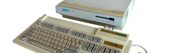
The trouble with being an incidental witness to the start of something that later becomes world-changing is that at the time you are rarely aware of what you are seeing. Take the Acorn Archimedes, the home computer for which the first ARM processor was developed, and which has just turned 30. If you were a British school pupil in 1987 who found a pair of the new machines alongside the row of BBC Micros in the school computer lab, for sure it was an exciting event, after all these were the machines everyone was talking about. But the possibility that their unique and innovative processor would go on to spawn a line of successors that would eventually power so much of the world three decades later was something that probably never occurred to spotty ’80s teens.

[Computerphile] takes a look at some of the first Archimedes machines in the video below the break. We get a little of the history and a description of the OS, plus a look at an early model still in its box and one of the last of the Archimedes line. Familiar to owners of this era of hardware is the moment when a pile of floppies is leafed through to find one that still works, then we’re shown the defining game of the platform, [David Braben]’s Lander, which became the commercial Zarch, and provided the template for his Virus and Virus 2000 games.
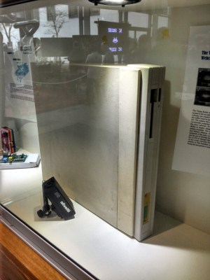
The Trojan Room Coffee Cam Archimedes, on display at the Cambridge University Computing Department.

We see the RiscOS operating system booting lightning-fast from ROM and still giving a good account of itself 20 years later even on a vintage Philips composite monitor. If you were that kid in 1987, you were in for a shock when you reached university and sat down in front of the early Windows versions, it would be quite a few years before mainstream computers matched your first GUI.

The Archimedes line and its successors continued to be available into the mid 1990s, but faded away along with Acorn through the decade. Even one being used to power the famous Trojan Room Coffee Cam couldn’t save it from extinction. We’re told they can still be found in the broadcast industry, and until fairly recently they powered much of the electronic signage on British railways, but other than that the original source of machines has gone. All is not lost though, because of course we all know about their ARM joint venture which continues to this day. If you would like to experience something close to an Archimedes you can do so with another computer from Cambridge, because RiscOS is available for the Raspberry Pi.

Sit back and enjoy the video, and if you were one of those kids in 1987, be proud that you sampled a little piece of the future before everyone else did.
Continue reading “The Acorn Archimedes At 30”

Laser Exposing PCBs With A Blu-Ray Laser

For those of us whose introduction to PCB making came decades ago and who share fond memories of permanent markers and crêpe paper sticky tape, the array of techniques available to PCB artists of today seem nothing short of magical. Toner transfer and peroxide etchant mixtures might seem run-of-the-mill to many readers, but even they are streets ahead of their predecessors from times past.

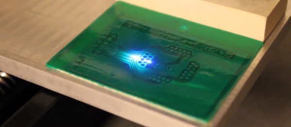
Photographic exposure of  etch-resist coating has traditionally been performed with a UV lamp through a sheet of acetate film, but there is no reason why that should be the only way it can be performed. There have been plenty of projects using lasers or LEDs to draw a PCB design onto the coating as a raster, and a rather nice example from [Terje Io] using a Blu-Ray laser diode is the subject of the video below the break.

The diode is mounted on a gantry with a THK KR33 linear actuator that he tells us was unsuitable for his CNC mill due to backlash. This gives a claimed 1200 dpi resolution, over a 100 mm x 160 mm exposure area. Software is provided in a GitHub repository, taking a PNG image exported through a PDF printer. And since it’s got a UV laser, it can be used in a second pass to process UV-responsive soldermask film. ([Terje] cheats and uses a separate CNC mill to drill out the holes.) The result looks great.

Continue reading “Laser Exposing PCBs With A Blu-Ray Laser”

Hackaday Prize Entry: Open Narrowband RF Transceiver

We have so many options when we wish to add wireless control to our devices, as technology has delivered a stream of inexpensive devices and breakout boards for our experimentation. A few dollars will secure you all your wireless needs, it seems almost whatever your chosen frequency or protocol. There is a problem with this boundless availability though, they can often be rather opaque and leave their users only with what their onboard firmware chooses to present.

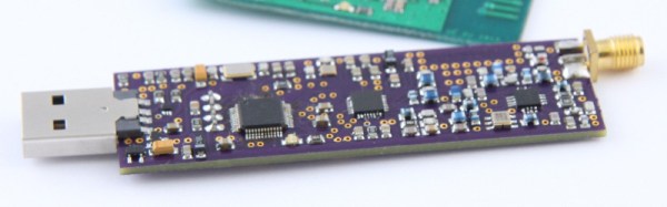
The Open Narrowband RF Transceiver from [Samuel Žák] promises deliver something more useful to the experimenter: an RF transceiver for the 868 or 915MHz allocations with full control over all transmission parameters. Transmission characteristics such as frequency, bandwidth, and deviation can be adjusted, and the modulation and encoding schemes can also be brought under full control. Where a conventional module might simply offer on-off keying or frequency shift keying, this module can be programmed to deliver any modulation scheme its chipset is capable of. Spread-spectrum? No problem!

Onboard, the device uses the TI CC1120 transceiver chip, paired with the CC1190 front end and range extender. Overseeing it all is an ST Microelectronics STM32F051 microcontroller, which as you might expect is fully accessible to programmers. Interfaces are either USB, through an FTDI serial chip, or directly via a serial port.

There are a host of transceiver chips on the market which just beg to be exploited, so it is very good indeed to see a board like this one. It’s worth noting though that the CC1120 has a much wider frequency band than that of the CC1190, and with a different front end and PA circuitry, this could cover other allocations including some amateur bands.

Retrotechtacular: London Bus Overhaul

If you have ever visited London as a tourist, what memories did you take away as iconic of the British capital city? The sound of Big Ben sounding the hour in the Elizabeth Tower of the Palace of Westminster perhaps, the Yeoman Warders at the Tower of London, or maybe the guardsmen at Buckingham Palace. Or how about the red double-decker buses? They’re something that, while not unique to the city, have certainly become part of its public image in a way that perhaps the public transport of other capitals hasn’t.

A city the size of London has many thousands of buses in the fleet required to provide transport to its sprawling suburbs. Until a few years ago the majority of these machines were built to a series of standard designs under the London Transport banner, so a Londoner with an eye for buses could have seen near-identical vehicles in any corner of the city. Each of these buses would have carried millions of passengers over hundreds of thousands of miles in a typical year, so many in fact that every few years they would have required a complete overhaul. For that task, London Transport maintained a dedicated factory capable of overhauling hundreds of buses simultaneously, and this factory is our subject today.

The overhaul works at Aldenham was the subject of a 1957 British Transport Films picture, Overhaul, in which we follow a bus in its journey through the system from tired-out to brand-new. We see the bus given a thorough inspection before being stripped of its upholstery and then having its body separated from its chassis and cleaned, then we see each part being refurbished. Along the way we gain a fascinating insight into the construction of a mid-century passenger transport vehicle, with its wooden frame and aluminium exterior panels being refurbished and rebuilt where necessary, before the camera. Meanwhile we see the chassis, with its separate gearbox in the centre of the vehicle, before it is painted to resist more years of road grime and reunited with a bus body. The completed vehicle is then taken for a test run before being sent to the paint shop for a coat of that iconic London Transport red. Enjoy the film in its entirety below the break.

The buses in the film are the AEC/London Transport “RT” vehicles, which entered service in the late 1930s and last ran in the 1970s. Their replacement, the visually similar “Routemaster” had only started to appear the previous year, and continued in regular service until 2005. Meanwhile the Aldenham bus overhaul works survived until its closure in 1986 due to the appearance of a range of new buses in the capital that did not conform to the standard design that it had been designed to serve.

Continue reading “Retrotechtacular: London Bus Overhaul”

Places To Visit: Electric Mountain

The experience of being a teenager leaves a host of memories, of social awkwardness in the difficult process of not quite being a child any more, of tedious school days, and of team sports seemingly enjoyed only by the few. Wherever in the world you grew up will have lent a particular flavour to your recollections of that period of your life, whether your memories are good or bad.

One surprising common theme in British teenage memories, at least those of a few decades ago, are power stations. In the 1970s and 1980s, the Central Electricity Generating Board had a PR effort that involved bringing parties of teenage school geography students in for a tour of their local electricity plant, so if you talk to a British person of a certain age you’ll probably find they’ve been up close and personal with a coal-fired power station.

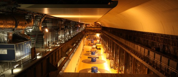
The true power station marvel of the age would have been too far away to tour for most kids at the time, though our geography teachers expounded on it at length. Dinorwig pumped-storage power station in Wales was opened in the early 1980s, and is a hydroelectric plant that uses excess grid generating capacity in the middle of the night to pump water into a lake at the top of a mountain, from which it can later be released at very short notice to respond to demand surges in a matter of seconds. The oft-quoted example is that when an episode of Coronation Street draws to a close there are several million British kettles turned on simultaneously, at which point Dinorwig comes online to rapidly make up the resulting shortfall.

Continue reading “Places To Visit: Electric Mountain”

Rescuing A Proprietary Battery Pack With A Cell From A Camera

If you have an older handheld battery-powered device, you may be fighting a diminishing battery capacity as its lithium-ion cells reach the end of their life. And if you are like [Foxx D’Gamma], whose device is an Alinco DJ-C7 handheld transceiver, you face the complete lack of availability of replacement battery packs. All is not lost though, because as he explains in the video below the break, he noticed that a digital camera battery uses a very similar-sized cell, and was able to graft the camera battery into the shell of the Alinco pack.

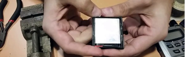
Cracking open the Alinco pack, he was rewarded with the rectangular Li-Ion cell and two PCBs, one for the connector and another for the battery management circuitry. By comparison the camera battery had a much smaller battery management PCB, and it fit neatly into the space vacated by the Alinco cell once those covers had been removed. A fiddly soldering job to attach the connector PCB, and he was rewarded with a working Alinco pack and an unexpected bonus when he found out that the transceiver was a dual band model.

Along the way he’s at pains to point out the safety aspects of handling Li-Ion cells, and to ensure that the polarity of the cell is correct. It’s also worth our reminding readers that these packs must always be accompanied by their battery management circuitry. The result though is pleasing: a redundant piece of equipment made obsolete by a proprietary battery, given a new lease on life.

Continue reading “Rescuing A Proprietary Battery Pack With A Cell From A Camera”

A Live ECU Simulator For OBD2 Projects

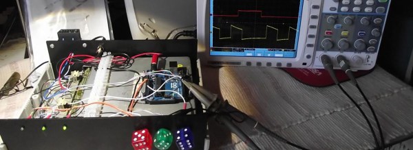
If you are working with OBD2 hardware or software, it’s easy enough to access test data, simply plug into a motor vehicle with an OBD2 socket. If, however, you wish to test OBD2 software under all possible fault conditions likely to be experienced by an engine, you are faced with a problem in that it becomes difficult to simulate all faults on a running engine without breaking it. This led [Fixkick] to create an OBD2 simulator using a secondhand Ford ECU supplied with fake sensor data from an Arduino to persuade it that a real engine was connected.

The write-up is quite a dense block of text to wade through, but if you are new to the world of ECU hacking it offers up some interesting nuggets of information. In it there is described how the crankshaft and camshaft sensors were simulated, as well as the mass airflow sensor, throttle position, and speedometer sensors. Some ECU inputs require a zero-crossing signal, something achieved with the use of small isolating transformers. The result is a boxed up unit containing ECU and Arduino, with potentiometers on its front panel to vary the respective sensor inputs.

We’ve brought you quite a few OBD2 projects over the years, for example, there was this LED tachometer, and a way into GM’s OnStar.

Thanks [darkspr1te] for the tip.