If you were a child of the late 1980s or early 1990s, the chances are you’ll be in either the Super Nintendo or the Sega Genesis/Mega Drive camp. Other 16-bit games consoles existed, but these were the ones that mattered! The extra power of the Nintendo’s souped-up 16-bit 6502 derivative or the Sega’s 68000 delivered a gaming experience that, while it might not have been quite what you’d have found in arcades of the day, was at least close enough that you could pretend it was.
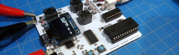
The distinctive sound of consoles from that era has gained a significant following in the chiptunes community, with an active scene composing fresh pieces, and creating projects working with them. One such project is [jarek319]’s Sega Genesis native hardware chiptune synthesiser, in which music stored as VGM files on a MicroSD card are parsed by an ATSAMD21G18 processor and sent to a YM2612 and an SN76489 as you’d have found in the original console. The audio output matches the original circuit to replicate the classic sound as closely as possible, and there is even some talk about adding MIDI functionality for this hardware.
The software is provided, though he admits there is still a little way to go on some functions. The MIDI support is not yet present, though he’s prepared to work on it if there was enough interest. You really should hare this in action, there is a video which we’ve placed below the break. Continue reading “Sega Genesis Chiptunes Player Uses Original Chips”→
In the years since the launch of the original Raspberry Pi we have seen the little British ARM-based board become one of the more popular single board computers in the hobbyist, maker, and hacker communities. It has retained that position despite the best efforts of other manufacturers, and we have seen a succession of competitor boards directly copying it by imitating its form factor. None of them have made a significant dent in the sales figures enjoyed by the Pi, yet they continue to appear on a regular basis.
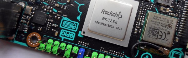
We recently brought you news of the latest challenger in this arena, in the form of the Asus Tinker Board. This is a board that has made us sit up and take notice because unlike previous players this time we have a product from a giant of the industry. Most of us are likely to own at least one Asus product, indeed there is a good chance that you might be reading this on an Asus computer or monitor. Asus have made some very high quality hardware in their time, so perhaps this product will inherit some of that heritage. Thus it was with a sense of expectation that we ordered one of the first batch of Tinker Boards, and waited eagerly for the postman.
Update:
A member of the Asus Marketing team read this review and contacted Hackaday with some updated information. According to our discussion, the Tinker Board has not officially launched. This explains a lot about the current state of the Tinker Board. As Jenny mentions in her review below, the software support for the board is not yet in place, and as comments on this review have mentioned, you can’t source it in the US and most other markets. An internal slide deck was leaked on SlideShare shortly after CES (which explains our earlier coverage), followed by one retailer in the UK market selling the boards ahead of Asus’ launch date (which is how we got our hands on this unit).
Asus tells us that they are aiming for an end of February launch date, perhaps as soon as the 26th for the United States, UK, and Taiwan. Other markets might have some variation, all of this contingent on agreements with and getting stock to regional distributors. With the launch will come the final OS Distribution (TinkerOS based on Debian), schematics, mechanical block diagrams, etc. Asus tells Hackaday it is a top priority to deliver hardware video acceleration for the Rockchip on the Tinker Board. The Board Support Package which hooks the feature into Linux is not yet finished but will come either on launch day or soon after. This is the end of the update, please enjoy Jenny List’s full review below.
Wherever you may live in the world, who do you wish to smile upon you and deliver good fortune? You may be surprised to discover that for a significant number of Brits this role is taken by someone called [Ernie].
What, [Jim Henson]’s Ernie from Sesame Street‘s famous duo Bert and Ernie? Sadly not, because the owner of a [Rubber Duckie] can’t offer you the chance of a million quid every month. Instead, [Ernie] is a computer that has been anthropomorphised in the national imagination. More properly referred to as E.R.N.I.E, for Electronic Random Number Indicator Equipment, he is the machine that picks the winning bond numbers for the Premium Bonds, a lottery investment scheme run by the British Government.
Brits have been able to buy £1 bonds, up to 50,000 of them today, since the 1950s, and every month they are entered into a drawing from which ERNIE picks the winners. The top two prizes are a million pounds, but for most bond holders the best they can hope for is the occasional £25 cheque. Premium Bonds are often bought for young children so a lot of Brits will have a few, often completely forgotten. Prizes never expire, so if you are the holder of old bonds you should consider asking National Savings and Investments whether anything is owed to you.
The Great Grandfather of Premium Bond Drawings
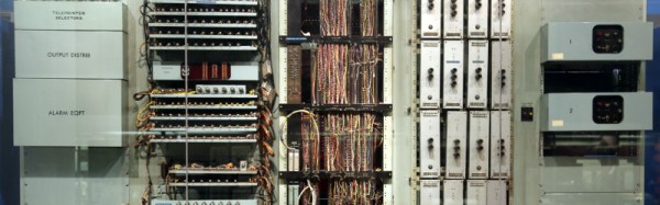
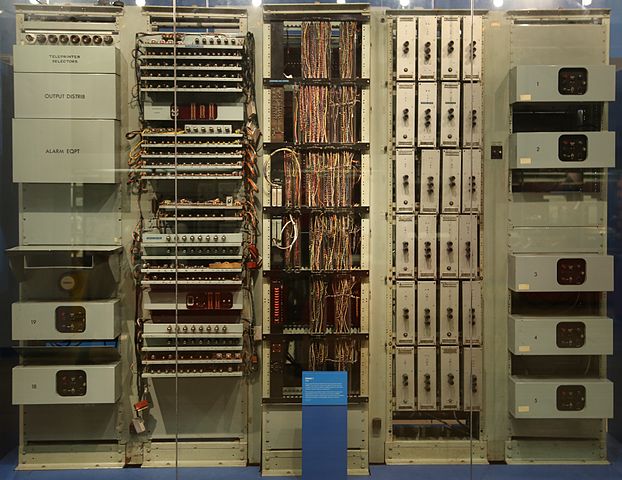
The original 1957 ERNIE, now in the collection of the Science Museum, London. Geni [CC BY-SA 4.0-3.0-2.5-2.0-1.0, via Wikimedia Commons.The current ERNIE is the fourth-generation model, but our attention today is on its 1950s ancestor. In a way it’s the most interesting of the machines because it has an unusual pedigree, being a creation of the Post Office Research Station, at Dollis Hill, London. As such it came from the lab of the Colossus engineer [Tommy Flowers], and is described as being a descendant of the now-famous but then still top-secret first digital computer used by the World War Two codebreakers. It’s thus a fascinating study for the student of computer history as well as for its role in British postwar social history, because it represents the only glimpse (had they known it at the time) that the British public had of the technology that had helped them so much a decade earlier.
A significant effort was made to ensure that the draw was truly random, and the solution employed by [Flowers] and his team was thoroughly tested before each draw. The thermionic noise generated across a neon tube was sampled, and this random voltage delivered the truly random numbers used to generate the winning bond numbers. The machine’s construction is extremely reminiscent of its wartime predecessor, however it is as well to bear in mind that it owes this to the standard racking and paint used in British telephone exchanges of the day. Gone though are the octal tubes, and in their place are their more familiar miniature successors.
We have two films for you showing this incarnation of ERNIE in action. The first is a National Savings promotional film which explains ERNIE’s purpose, while the second shows us the Minister of the time starting the first draw. Believe it or not, this was a cause of major national excitement at the time.
If you’ve ever cast your eye towards the rooftops, you’ll be familiar with the Yagi antenna. A dipole radiator with a reflector and a series of passive director elements in front of it, you’ll find them in all fields of radio including in a lot of cases the TV antenna on your rooftop.
In the world of amateur radio they are used extensively, both in fixed and portable situations. One of their most portable uses comes from the amateur satellite community, who at the most basic level use handheld Yagi antennas to manually track passing satellites. As you can imagine, holding up an antenna for the pass of a satellite can be a test for your muscles, so a lot of effort has gone into making Yagis for this application that are as lightweight as possible.
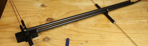
[Tysonpower] has a contribution to the world of lightweight Yagis, he’s taken a conventional design with a PVC boom and updated it with a stronger and lighter boom made from carbon fibre composite pipe. The elements are copper-coated steel welding rods, some inexpensive aluminium clamps came from AliExpress, and all is held together by some 3D-printed parts. As a result the whole unit comes in at a claimed bargain price of under 20 Euros.
This antenna is for the 2 M (144 MHz) amateur band, but since it’s based on the [WB0CMT] “7 dB for 7 bucks” (PDF) design it should be easily modified for other frequencies. The 3D printed parts can be found on Thingiverse, and he’s also posted a couple of videos in German. We’ve posted the one showing the build below the break, you can find the other showing the antenna being tested at the link above.
Have you ever had a laptop you just wish you didn’t have to retire when its specification becomes to aged for your needs? Wouldn’t it be great if you could upgrade it and keep using the physical hardware!
[Alpinedelta] has a vintage Toshiba T1000 laptop, roughly a PC-XT clone from the late 1980s. Its 80C88 processor, CGA display, and 512k of memory make it a museum-piece, but he has plans to modernise it using a LattePanda Intel Atom based single board computer.
To make that happen, he has to ensure all the Toshiba’s peripherals will talk to a modern host. Unfortunately back in the 1980s many PC clones were clones in a rather loose sense, and especially so in the laptop arena. Thus there are no handy standard PC interfaces and since USB was several years away at the time, nothing the LattePanda can talk to directly. His solution for the keyboard is to wire its matrix directly to a Teensy microcontroller that then provides a USB interface, and he’s put up a useful step-by-step Instructables guide.
There is no standard for a laptop keyboard matrix, so the first and most tedious task is to unpick its layout.This he did by identifying each trace and assigning a different rainbow colour to it, before noting down which keys appeared on it and collating the results in a spreadsheet. The different colours of wire could then be assigned to the colours of a piece of rainbow ribbon cable, and wired in sequence to the Teensy’s I/O pins. There then follows a step in the software in which he assigns the pin mappings to the lines in his spreadsheet, then the sketch can be compiled and uploaded to the Teensy. Result: a vintage keyboard now talking USB.
Using a Teensy to present a USB keyboard to the world is a well-worn path, we’ve seen it with both newer keyboards and other relics like this one from a DEC VT100.
The International Space Station, or ISS, has been in orbit in its various forms now for almost twenty years. During that time many of us will have stood outside on a clear night and seen it pass overhead, as the largest man-made object in space it is clearly visible without a telescope.
Most ISS-watchers will know that the station carries a number of amateur radio payloads. There are voice contacts when for example astronauts talk to schools, there are digital modes, and sometimes as is happening at the moment for passes within range of Moscow (on Feb. 14, 11:25-16:30 UTC) the station transmits slow scan television, or SSTV.
You might think that receiving SSTV would be hard work and require expensive equipment, but given the advent of ubiquitous mobile and tablet computing alongside dirt-cheap RTL-SDRs it is now surprisingly accessible. An Android phone can run the SDRTouch software defined radio app as well as the Robot36 SSTV decoder, and given a suitable antenna the pictures can be received and decoded relatively easily. The radio must receive 145.8MHz wideband FM and the decoder must be set to the PD120 PD180 mode (Thanks [M5AKA] for the update), and here at least the apps are run on separate Android devices. It is possible to receive the signal using extremely basic antennas, but for best results something with a little gain should be used. The antenna of choice here is a handheld [HB9CV] 2-element beam.
A failed grab from a 2015 transmission, proving that Hackaday scribes don’t always get perfect results.
You can find when the station is due to pass over you from any of a number of ISS tracker sites, and you can keep up to date with ISS SSTV activity on the ARISS news page. Then all you have to do is stand out in the open with your receiver and computing devices running and ready, and point your antenna at the position of the station as it passes over. If you are lucky you’ll hear the tones of the SSTV transmission and a picture will be decoded, if not you may receive a garbled mess. Fortunately grabs of other people’s received pictures are posted online, so you can take a look at what you missed if you don’t quite succeed.
Even if you don’t live within range of a pass, it’s always worth seeing if a Web SDR somewhere is in range. For example this Russian one for the current transmissions.
In that you are using off-the-shelf hardware and software you might complain there is little in the way of an elite hack about pulling in a picture from the ISS. But wait a minute — you just received a picture from an orbiting space station. Do that in front of a kid, and see their interest in technology come alive!
We’ve seen a variety of home-made laptops using the Raspberry Pi and other single board computers over the years. Usually, they combine off-the-shelf USB keyboards and trackpads with HDMI monitor panels, and cases made from layered laser cut sheet, or 3D printed plastic.
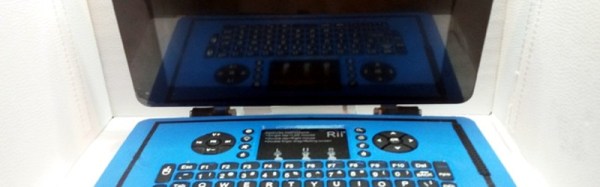
[Surferboy]’s Raspberry Pi laptop is the latest effort to come before us, and its claim to fame is the use of the official Raspberry Pi 7″ touchscreen as a display. Full instructions and 3D printer files are available on Thingiverse so you can have a go at replicating it if a portable Pi is your thing.
He’s taken the bold step of not attempting to place all the Pi’s interfaces next to the outside of the case. Instead, he’s desoldered the Ethernet and USB ports. The USB connections were wired directly to the keyboard, display, and a couple of external ports on the right-hand side of his case. This leaves the finished laptop with no Ethernet. However, losing ethernet is a worthy tradeoff for the thinner package.
[Surferboy] also brought the GPIO header to a female socket on the rear of the unit. It’s unclear exactly what battery he uses except for a reference to the battery from his keyboard. Since a keyboard battery will be too small for Pi and display we are guessing a larger pack will be necessary.
Though the Ethernet port and battery issue would probably be a dealbreaker here this has the makings of a useful and compact laptop, it will be interesting to see if it is picked up and refined by the community.