
UPDATE 1/21/14 3:20pm: We’re sold out! See you at the party! Here are directions! Doors open at 6!
UPDATE 1/21/14 3:20pm: We’re sold out! See you at the party! Here are directions! Doors open at 6!

![]()
[Nick] wrote in to tell us about his first blog post. He’s showing off a PWM LED driver he build around a 555 timer. This project uses a lot of basics; some 555 experience, PCB etching, and surface mount soldering. We’d like to know more about the blue substrate on his circuit board!
After seeing the BOM spreadsheet with KiCAD integration a couple of weeks back, [Vassilis] sent in a link to his own Excel-based Bill of Materials helper. We’re wondering if anyone has a similar tool that will work with Open Office?
While we’re on the topic of downloadable documents, here’s a reference PDF for all types of DC measurements. The collection is a free offering from Keithley. [Thanks Buddy]
Since you’re brushing up on your knowledge you may also be interested in a free online microcontroller course offered by UT Austin. They’re targeting the Tiva C Launchpad as the dev board for the class.
This website seems to be a little creepy, but the teardrop shaped 3D printed music box which is being shown off is actually rather neat.
Hackaday Alum [Phil Burgess] threw together a point and shoot camera for Adafruit. It’s a Raspberry Pi, camera board, touchscreen display, and USB battery all rubber banded together. The processing power of the RPi is used to add image processing effects which are shown off in the demo video.
We don’t own a DeLorean. If we did, we’d probably follow the lead of Queen’s University Belfast and turn it into and electric vehicle. [Thanks Jake]
The 3D photocopiers are coming. Here’s a hacked together proof-of-concept from [Marcelo Ruiz]. After laser scanning the part is milled from floral foam.

Looking at this huge Uninterruptible Power Supply we are a little envious. It’s meant to hang on the wall of a utility room and power your critical devices. [Radek Hvizdos] has had it in service for quite some time, and when he started thinking of replacing the internal battery he decided to see if he could also extend the functionality. To do so he needed to get at the firmware of the chip controlling the device. And so began his adventure of dumping the firmware from the read-protected PIC 18F452.
The challenge of dumping code from a write-protected chip is in itself a fun project. But [Radek] was actually interested in fixing bugs and adding features. The wishlist feature we’d be most interested in is a kind of triage for shutting down devices as the internal battery starts to run low. Nice! But starting from scratch with the firmware is a no-go. You can see the two places where he connected to the PCB. The upper is for using a PIC programmer. The lower is an I2C connection used to dump the EEPROM with an improvised Bus Pirate.
In the end it was improper lock bit settings that opened the door to grabbing the firmware. The bootloader section of the PIC is not locked, and neither is the ability to read from FLASH at run-time. These two combined allowed him to write his own code which, when flashed to the bootloader section, dumps the rest of the firmware so that it may be combined into a complete file afterward. Since posting this fascinating article he has made a follow-up about disassembling the code.
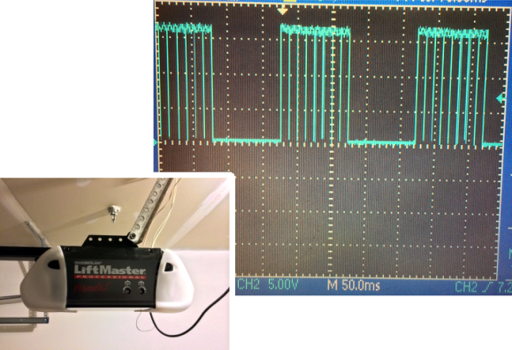
In addition to being something fun to do with an oscilloscope, this could be a valuable time-saver for anyone looking to tap into the wired communications on a garage door opener. If you own an older model you might be scratching your head. But newer units have more than just one button operation, usually extending to at least two extra buttons that control the lights on the motor unit and lock out wireless control. A quick probing turned up the communication scheme used by the button unit mounted next to the door into the house.
We’ve patched into our own garage door using a simple relay to interface with a microcontroller which will still work for opening and closing the door But if you’re looking for extended control you need to spoof one of the timing signals detailed in this post. We like the stated examples for future hacks: building a better wired button unit, or adding some type of RFID integration. We could see this approach for hacking in motion light control for door openers that don’t have it.
[Thanks Victor]
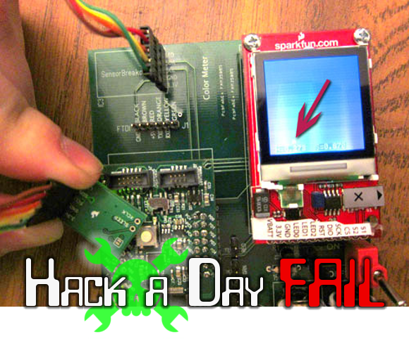
[John Peterson] answered our call to document your hacks by discussing what he learned while building this color meter. He conceived the project as a way to precisely match the color output of LEDs driven with a PWM signal. The thought was that it could sample an LED’s output, then use that data to calculate values necessary to match the color of other LEDs. This is a good idea when using LEDs of different types, but even diodes from the same production line can show variations in color output.
Of course this project wouldn’t be featured as a Fail of the Week if it worked as he had expected. It turns out the sensor that he used, an Avago ADJD-S371-QR999 on a SparkFun breakout board, takes very quick color readings. This is great for solid objects, but not great for a light source being switched on and off like the PWM LEDs.
We like it that [John] posted a list of lesson learned on the project. The real fail is in trying to use this particular sensor, but we figure there must be some way to get meaningful data through sampling. Check out the page for the retired sensor which also includes a link to the datasheet. Can you think of a firmware hack which would allow this hardware to sample so that the PWM value could be extrapolated through averaging or other calculations? Let us know in the comments.
 Fail of the Week is a Hackaday column which runs every Wednesday. Help keep the fun rolling by writing about your past failures and sending us a link to the story — or sending in links to fail write ups you find in your Internet travels.

Building line following robots is fun and easy. Building a line-follower that is this tiny is a different story. The surprising thing for us is that despite how it looks, this robot whose name is Rizeh doesn’t use wheels to get around. [Naghi Sotoudeh] built the line-follower using two vibrating motors, with needles (not shown above) making three points of contact with the ground.
His website is a little sparse, but hit the downloads page to get a PDF file that serves as the build log. We also downloaded the 32 second demo video which is worth it. The magic-marker track that the bot is circumnavigating isn’t any bigger than the palm of your hand!
Onboard the diy PCB you’ll find two GP2S04 IR reflectance sensors which detect the black line on a white paper. The power-up sequence spends a few seconds calibrating these sensors. Speaking of power, [Naghi] went with a lithium polymer cell from a Bluetooth headset. At the heart of it all is an ATtiny45 which uses its hardware PWM capabilities to drive the two motors.
Of course line-followers rank up there with self-balancers as our favorite robot projects. But by far the ones we love the most are the speed-run maze solvers.


The Gathering is next Tuesday and we are starting to get excited about it! There is a waiting list of people who would like a ticket. If you registered for a ticket that you will not be able to to use, please log in and cancel it.
Cancelling your unused ticket will automatically free up a ticket for someone on the waiting list. Cancellation instructions are below. We want to pack the house and making sure no ticket goes unused is important.
Still want to attend? It’s not too late. Add yourself to the waiting list.


