Helicopter POV Display Is A Masterwork

helicopter hack LED mod

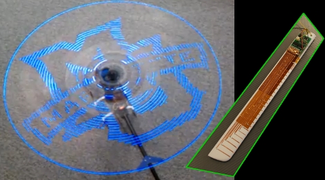
Yes! A radio control helicopter with a fairly high-resolution persistence-of-vision display is a beautiful thing. [Mziwisky’s] handiwork is the result of several steps along the prototyping path. He built up a POV test rig on a breadboard, designed his first PCB for the project, and then went to work building it. After initially being inspired by a POV ceiling fan [Mziwisky] looked around to see if anyone else had already added a display to a helicopter. Indeed, this has been done before but there were very few details on the build.

The helicopter has two blades and each have the same hardware on them and gobbled up about ten hours of assembly time each. He basically built a printed circuit board using the blades as a substrate by attaching adhesive copper foil. This makes up the matrix for the LEDs and connects to a small circuit board with an ATmega8 and some shift registers mounted on the inside end of the blade. There’s also a 180 mAh LiPo battery pack, and a hall effect sensor to synchronize the display on each. The results are spectacular, as you can see in the video after the break, but there’s a few bugs left to work out in order to fully tame the 32 LEDs on each rotor.

Kind of looks like the future is happening right now.

Continue reading “Helicopter POV Display Is A Masterwork”

Building A Wooden Vespa

Scooter fans should start sharpening their chisels if they want to undertake this project. This Vespa is the work of a master carpenter and a lot of time. Through the build log photos you can see that it all started with a frame made by bending and laminating wood layers together. Veneer adds the stylish stripe and a lot of carving and turning brings the curves associated with the classic scooters. Even the hand grips, brake handles, and saddle are made out of wood. There’s springs for some shock absorption but we’d bet you don’t want to ride this for too long, or park it outside. Now it just needs an electric motor retrofit.

[Thanks Blair]

Under-desk RGB Keyboard Lighting

[Jay Collett] was having trouble seeing his keyboard when the room was dim. But throwing a light under the desk just didn’t seem cool enough. Instead he built an RGB light board that is controlled by his desktop. The board is based around an ATmega328 with the Arduino booloader. He etched a single-sided PCB to connect it to a group of five RGB LEDs, with a programming header for an FTDI cable. The board communicates with a PC via serial connection, with a C# control application that [Jay] coded to control the color. We’ve embedded a couple of videos after the break but check his page for a package of code and hi-res pictures.

If you want something cool that’s a little bit less work to build check out the EL-wire keyboard from this links post.

Continue reading “Under-desk RGB Keyboard Lighting”

DIY Vaporizer

Here’s a DIY vaporizer build. It uses a 30 watt Radio Shack soldering iron as a heat source that is regulated with a common dimmer switch. This is done by removing the soldering tip and replacing it with threaded rod attached to a brass pipe fitting assembly. This is housed inside of a Mason jar with a copper pipe for air intake and another for output. Not surprisingly the creator tipped us off anonymously, saying that this a “smoking accessory”. A bit of searching and we came across this Wikipedia article about a Volcano Vaporizer which sheds light on what one is used for.

We don’t condone using illicit substances. But even more so, we’re skeptical about breathing through this thing because of the warning that [Anon] included about noxious vapors put off by the epoxy putty when it heats up. Still, it’s an interesting build so we though we’d share.

Gum Ball Maze Updated… Now With Robots!

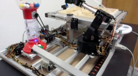
In what is surely becoming an ever-growing Rube Goldberg machine, [Dan] updated his gum ball dispenser to include a robot arm. We looked in on this human lab-rat experiment that rewards successful maze navigation with bubble-gum just about a year ago. As you can seen in the video after the break he’s added several new features to delight users. The original had a maze actuated by an accelerometer and that remains the same. But when the device fires up, the wooden ball is moved to the start of the maze by a Lynxmotion robotic arm. That arm is mounted on rails so it can also move to deliver the gum ball after a successful run. There’s also an anti-jamming feature that shakes the gum ball dispenser to ensure you don’t come up empty.

Whether playing chess or being controlled by a mouse the Lynxmotion has been quite popular lately. [Dan’s] solution uses a vacuum pump to grab onto the spheres (both wooden and gum), similar to the method used with the CNC pick and place from a while back.

Continue reading “Gum Ball Maze Updated… Now With Robots!”

Dungeon Crawler Game For IM-ME (and Linux)

[Joby Taffey] takes the prize for the first completed homebrew game for the IM-ME. Over the last few weeks we’ve seen [Travis Goodspeed] working with sprite graphics, and [Emmanuel Roussel] developing game music for the pink pager. But [Joby] didn’t really use either of those.

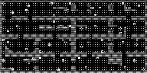
[Travis’] sprites were using a framebuffer that fills up a lot of valuable RAM. [Joby] decided to draw the room screens (all of them have been stitched together for the image above) as a one-time background image to keep the memory free. From there, the screen is updated in 8×8 blocks based on cursor movement. He also decided not to add music as he feels the high-pitched piezo is not capable making sound without driving everyone crazy.

Source code is available and for those of you who don’t own this pretty handheld, the game can also be compiled in Linux.

Moving A Resistor For EvalBot Power When Programming

[Riley Porter] posted a picture of his EvalBot USB power hack. In the photo above we’ve put a box around D6 and D7. The development board ships with a 0 Ohm resistor in the D7 location, patching in power from the USB-B connector labeled USB DEVICE. He found that by moving that resistor to D6 he can power the board from the USB-B connector labeled ICDI.

That connector is the In-Circuit Debug Interface. TI sent us an EvalBot bundle so we pulled it out and tried it ourselves. If you plug in the ICDI it doesn’t power the board, and no USB devices register. Shorting the D6 pads changes this and the following USB device registers:

Bus 002 Device 062: ID 0403:bcd9 Future Technology Devices International, Ltd Stellaris Evaluation Board

So it looks like you need to have two USB connections or be using batteries in order to program the board via USB. The uC/OS-III hardcover book that ships with the EvalBot bundle includes board schematics. We took a look and were surprised to see that they show diodes installed on both pads. Rev A of the online schematics have been corrected, showing an omitted diode on D6 and the 0 Ohm resistor on D7. Images of both schematics are included after the break.

It would have been nice to see a selector switch installed here to give you a little more flexibility when prototyping.

Continue reading “Moving A Resistor For EvalBot Power When Programming”