A Game Boy built out of copper wires

The Wonderfully Weird Wireframe Game Boy That Actually Works

We see lots of great hardware projects here at Hackaday: some are extremely clever, some are beautifully made, and some show off their maker’s extraordinary skills. Others are just plain weird, but still manage to include some or even all of the above categories. Case in point: [kgsws]’s Wireframe Game Boy project. It’s probably the weirdest Game Boy mod we’ve seen so far, but also extremely impressive from a technical point of view.

The basic idea was to take a Game Boy Pocket and remove its outer shell, replacing it with a cage-like structure made from thick copper wire. That sounds kind of reasonable; think of those transparent Game Boys, only without the transparent plastic. [kgsws]’s video (embedded below) shows him bending a few pieces of copper wire to match the Game Boy’s overall shape, then adding mounts for the cartridge socket, the display, the D-pad and the four buttons. After that you’d simply slide in the PCB, insert some batteries and off you go, right?

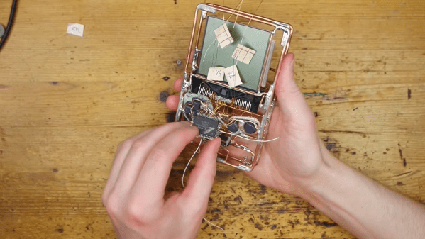
Well, this wouldn’t do for [kgsws]. What he did instead, was use a hot air desoldering station to remove all chips from the motherboard and proceed to mount them directly inside the wireframe without a PCB. He then used dozens of thin copper wires to hook up the cartridge slot, the CPU, RAM, buttons, and everything else to reconstruct the motherboard’s functionality. We cringed a bit when we saw him brutally cut the display’s flat cable with scissors, and that too was connected to the rest of the system through flying wires, soldered directly onto the screen’s contacts.

Amazingly, the system managed to boot up and run its software after it got a pair of fresh batteries. Despite a slightly dodgy D-pad, the naked Game Boy actually turned out to be fully usable, although it probably requires somewhat more delicate handling than Nintendo’s famously bullet-proof hardware. We’ve seen Game Boys modded into all kinds of different shapes and sizes, but none quite as unusual as today’s. If it’s wireframe construction you like, check out this eerie sound generator or this beautiful circuit sculpture clock. Continue reading “The Wonderfully Weird Wireframe Game Boy That Actually Works”

A system that stores data on LEGO bricks

How To Use LEGO Bricks For Data Storage

Those old enough to have encountered punch cards in their lifetime are probably glad to be rid of their extremely low data density and the propensity of tall stacks to tip over. But obsolete as they may be, they’re a great tool to show the basics of binary data storage: the bits are easily visible and can even be manipulated with simple tools. As an experiment to re-create those features in a more modern system, [Michael Kohn] made a punch card-like system based on LEGO bricks that stores machine code instructions for a 65C816 CPU, the 16-bit successor to the venerable 6502.

Bits are stored on a white 8×20 stud board, onto which small black pieces are placed. A white background stud encodes a logic “zero”, while a black stud encodes a logic “one”. The bits are read out by an array of reflectance sensors, which conveniently has the same 8 mm pitch as standard LEGO studs. A big wheel driven by a stepper motor slides the data card under the readout circuit along a short stretch of LEGO train tracks.

The optical sensors are read out by an MSP430 series microcontroller, which also drives the motor through a stepper motor driver. Once the data is read out, the bytes are transferred into a WDC W65C265SXB board, which executes them as machine code instructions on its 65C816 CPU. In the video below, you can see a program being loaded that blinks an LED.

We’ve featured educational punch-card systems before, like this Raspberry Pi-based model. If you’ve got a bunch of actual punch cards that need reading out, check out this Arduino-powered readout system.

Continue reading “How To Use LEGO Bricks For Data Storage”

A brick mailbox with a LIDAR sensor mounted inside

Using A LIDAR Sensor To Monitor Your Mailbox

The inconvenience of having to walk to your mailbox to check for mail has inspired many hackers to install automated systems that let them know when the mail has been delivered. Mailbox monitors have been made based on several different mechanisms: some measure the weight of the items inside, some use cameras and machine vision, while others simply trigger whenever the mailbox’s door or flap is moved. When [Gary Watts] wanted to install a notification system for his 1940s brick letterbox, his options were limited: with no flap or door to monitor, and limited space to install mechanical contraptions, he decided to use a LIDAR sensor instead.

Probably best-known for their emerging application in self-driving cars, LIDAR systems send out a laser pulse and measure the time it takes for it to be reflected off a surface. In the case of [Gary]’s mailbox, that surface is either the brick wall or a letter leaning against it. Since letters are inserted through a vertical slot, they will usually be leaning upright against the wall, providing a clear target for the laser.

The LIDAR module, a VL53L0X made by ST, is hooked up to a Wemos D1 Mini Pro. The D1 communicates with [Gary]’s home WiFi through an external antenna, and is powered by an 18650 lithium battery charged through a solar panel. The whole system is housed inside a waterproof plastic case, with the LIDAR sensor attached to the inside of the mailbox through a 3D-printed mounting bracket. On the software side, the mailbox notifier is powered by Home Assistant and MQTT. The D1 spends most of its time in deep-sleep mode, only waking up every 25 seconds to read out the sensor and send a notification if needed.

We’ve seen quite a few fancy mailbox monitors over the years: some are extremely power efficient, some use multiple sensors to allow for different use-cases, and some others are simply beautifully designed.

A pair of purple PCB-based game controllers on a solderless breadboard

Odd Inputs And Peculiar Peripherals: The GameBug Turns Your Breadboard Into A Game Console

What’s more fun than playing video games? Designing your own video game hardware, of course! If you’ve followed these pages long enough you’ll have seen dozens of great examples of homebrew hardware, and perhaps been inspired to try such a project yourself. This often starts with assembling the basic bits onto a solderless breadboard, which is fine for programming but not so great for testing: squeezing pushbuttons into your breadboard works for basic debugging, but is not very user-friendly or reliable. A better solution can be found in [Dimitar]’s GameBug: a set of breadboard-compatible joypad-like controllers.

The GameBug’s design excels in its simplicity: a miniature analog joystick, four buttons arranged in a diamond pattern, a shoulder button and two sliding switches are sitting on a neat purple PCB. On the bottom are two rows of pin headers to ensure a snug fit on your solderless breadboard. There’s even a little vibrating motor for haptic feedback.

Interfacing with the GameBug is simplified by the integrated readout electronics. A Schmitt trigger-based debounce circuit ensures clean signals from all the pushbuttons, while a motor driver chip provides stable current to the haptic feedback system. An RGB LED can be used as yet another user feedback device, or simply for decorative lighting.

All design files are available on [Dimitar]’s GitHub page, along with an Arduino sketch to help you try out the GameBug’s functionality. Having a proper gamepad might come in handy with breadboard-based game systems like Tiny Duck Hunt or this impressive mess of wires that makes up a Colecovision.

A pair of purple PCB-based game controllers

A wooden platform for a litter box

Track Your Cat’s Weight Through This Internet-Connected Litter Box

With feline obesity on the rise, keeping track of your cat’s weight is an important part of keeping them healthy. However, a weighing session can be anything from a routine job to a painful procedure, depending on your cat’s temperament. [Andy]’s cat Ellie is one of those who dislike being weighed, so in order to track her weight without drama [Andy] got creative and built an internet-connected weighing platform for her litter box.

The platform consists of two pieces of MDF held apart by two load cells, which are hooked up to an ESP8266. The ESP reads out the load cells and reports its findings to the Adafruit IO platform through its WiFi connection, sending updates to [Andy] whenever litter box use has been detected. The cat’s weight can be simply calculated by subtracting the weight of the unused litter box from the weight measured when it’s in use.

A smartphone pop-up message from an IoT litter boxGetting reliable readings from the load cells was a bit of a challenge, since the measured weight fluctuated wildly as Ellie moved around the litter box. A combination of waiting for the readings to settle and using timeouts to discard the effect of brief movements resulted in reasonably stable measurements. The resolution was even good enough to measure the difference in litter weight before and after use. We’re not sure what’s the practical value of knowing how much your cat poops each time, but if the data is there you might as well log it.

[Andy] also imagines smart-home features of the IoT litter box: for example, he could run an air purifier or send in the Roomba after heavy usage. This is not even the first internet-connected litter box we’ve featured; we’ve seen one connected to the Thingspeak platform, as well as one that sends poop alerts through Twitter. If you’re not around to clean up the mess, an automatic fume extractor might come in handy.

Continue reading “Track Your Cat’s Weight Through This Internet-Connected Litter Box”

A wood-and-plastic jig to make dovetail joints

3D Printed Template Makes Perfect Dovetail Joints

Dovetail joints on a piece of furniture are one of those features that make it say “master carpenter” rather than “IKEA”. Traditional hand-made dovetails require accurate measurements and even more accurate sawing and chiseling, skills that may take years to develop. A slightly less artisanal method is to use a router and a dovetail template; the router makes perfectly straight cuts while the template makes sure it goes only where it needs to go.

If you haven’t got one of those templates yet, check out [Guy Perez]’s design for an adjustable dovetail template that’s easy to produce with a 3D printer. It consists of ten separate pieces mounted on a T-rail, which enables them to slide sideways and thereby generate pins and tails of varying widths. The T-rail is mounted on a wooden body with an integrated clamp to hold the target piece, as well as an endstop to provide a reference for all measurements.

As you can see in the video embedded below, the resulting jig is easy to use and should result in near-perfect dovetails each time. [Guy] made the CAD files available as well as detailed instructions on their design, so you can easily adjust them if you need pieces with a different tail angle or want to use thicker wood.

While this jig will make cutting ordinary dovetail joints a lot easier, you can still show off your manual skills by making an impossible mallet. Want to join metal bits instead? Check out this cute little dovetail cube.

Continue reading “3D Printed Template Makes Perfect Dovetail Joints”

An electric eraser built into a mechanical pencil

Power Up Your Pencil With The 30,000 RPM Erase-O-Matic

There are some inventions that look completely pointless to the untrained eye: who would ever need a motorized garbage can, an electric pencil sharpener or a battery-powered eraser? Quite often, it turns out that there is some niche use case where such tools make complete sense, as is the case for motorized erasers. Having a tiny piece of rubber spinning at high speed gives artists and drafters a way to very precisely delete or lighten bits of their drawing, something that’s nearly impossible to do with a regular eraser.

[Franklinstein] however decided to design a high-speed eraser integrated into a mechanical pencil that brings the whole concept straight back to the pointless category, although not without showing off his advanced engineering skills. The Erase-O-Matic contains a miniature electric motor sourced from a quadcopter, together with an ultra-small lithium-ion battery and a power switch. The spinning bit is held by a tiny bearing, with the whole setup covered by a machined aluminium housing.

Tests with a laser tachometer show a rotational speed of about 30,000 RPM, which is almost three times as fast as a commercial electric eraser. And although it has very good erasing performance, it also wears out its tip in a few seconds, so a bit less speed could actually make this device more useful. If you’re planning to build one of these yourself, you might want to first read our primer on small DC motors.

Continue reading “Power Up Your Pencil With The 30,000 RPM Erase-O-Matic”