A hot tub with a smartphone in front showing real-time sensor data

ESP32 Keeps Track Of Hot Tub’s Vital Signs

Like swimming pools, hot tubs need regular monitoring to ensure their water stays clean and clear. An average person might take a water quality reading once or twice a week using test strips, but such a low sampling rate obviously won’t do for a hacker. [Stephen Carey] has therefore built a hot tub monitor that checks the water quality every minute and reports it on a neat mobile dashboard.

[Stephen]’s system uses commercially available sensors that track pH levels and Oxidation-Reduction Potential (ORP), both basic measurements that indicate water quality. A second set of sensors keeps track of the temperature of the water and the outside air, which should help in finding insulation failures and keeping energy use under control.

A set of graphs showing a hot tub's pH and ORP over time, with a significant spike in both near the beginningAn ESP32 reads the sensors and sends out the data through WiFi. [Stephen] programmed the ESP32 in MicroPython, using an MQTT driver to connect it to Home Assistant. By looking at the graphs generated, you can tell when someone entered the tub from a step change in pH and ORP. It’s even possible to generate alerts when any of the values drift outside their acceptable range – we can already imagine an alarm going off when someone enters without having showered first.

The system also has a calibration mode to check the sensors against a well-defined buffer solution. As with many chemical sensors, the pH and ORP probes gradually lose their active material and need to be replaced after about a year. Good ones aren’t cheap, but [Stephen] has found pretty decent low-cost alternatives on AliExpress that should be fine for a home setup.

If you also want your tub or pool to be actively managed, you’ll need a more complex system, perhaps even one that can also dispense chemicals. If your hot tub is heated by a wood fire, however, all you need is a way to alert the person tending the fire.

Overclocking Raspberry Pi 5’s SoC To 3 GHz And 1 GHz GPU

Overclocking computer systems is a fun way to extract some free performance, or at least see how far you can push the hardware before you run into practical limitations. The newly released Raspberry Pi 5 with BCM2712 SoC is no exception here, with Tom’s Hardware having a go at seeing how far both the CPU and GPU in the SoC can be pushed. The BCM2712’s quad Cortex-A76 CPU is normally clocked at 2.4 GHz and the VideoCore VII GPU at 800 MHz. By modifying some settings in the /boot/config.txt configuration file these values can be adjusted.

In order to verify that an overclock was stable, the Stressberry application was used, which fully loads the CPU cores. Here something like a combination of stress-ng and glxgears could also be used, to stress both the CPU and GPU. With the official actively cooled heatsink the CPU reached a temperature of 74°C with a whole board power usage of about 10 Watts. At idle this dropped to 3 Watts at 46°C. At these speeds, the multiple Raspberry Pi 5 units OCed by Tom’s Hardware were mostly stable, though one of the team’s boards experienced a few crashes. This suggests that this level of OCing could still be subject to luck of the draw, and long-term stability would have to be investigated as well.

As for the practical use cases of OCing your Raspberry Pi 5, benchmarks showed a marked uplift in compression and Sysbench benchmark scores, but OCing the GPU had no real positive impact on YouTube or 3D performance, leading even to a massive increase in dropped frames with video playback. This probably means that increasing the CPU clock may be beneficial, but OCing the GPU could be futile without also OCing the RAM frequency, if at all possible.

Realistically, the Raspberry Pi SoCs never were speed monsters, with even the Raspberry Pi 4B’s SoC being beaten handily in 2020 by a budget dual-core Intel CPU.  The current Intel Alder-Lake-N-based N100 SoC has a 6 Watt TDP and boosts up to 3.4 GHz while its Xe-LP-based iGPU (with AV1 decoding support) makes for a decent gaming experience within a ~16 Watt power envelope. Clearly, any OCing of the Raspberry Pi boards is more for the challenge of it, but then so is running the latest Intel CPU at 10 GHz with liquid nitrogen cooling.

A Spinning Egg For Your Thoughts

Brushless motors are fascinating devices that come in all sorts of shapes and sizes, but you’ve probably never seen one in the form of a free-spinning shiny metal egg. Created by [David Windestål], [Giacomo Di Muro], and [Chad Kapper], the Motion Zero is part top, part brushless motor, and fully mesmerizing. Tech overview video after the break.

Like the classic Tippe Top toy, an ovoid shape like this shiny metal egg will stand on its end if it’s spun fast enough. To do this, the team embedded magnets in the metal egg, effectively turning it into a rotor. An array of 4 PCB coils under a smooth concave surface serves as the stator. Because the egg is not held in position by a shaft, hall effect sensors were incorporated to determine the position of the egg, and properly control the state of the coils to keep it spinning.

Recognizing how easy it was to get lost in thought while staring at a shiny spinning egg, the rest of the device was designed with meditation in mind. The top cover is a block of aluminum machined with ripple patterns, with ball bearings that slide between the ripples as the control interface. Additional hall effect sensors on the PCB determine the position of the balls to adjust the rotation speed and shut-off timer. You can even choose to make the egg move around or remain in one position. The main controller is an ESP32 module, which reads all the hall effect sensors and controls the coils via motor drivers.

The Motion Zero has made its debut on Kickstarter and already exceeded its initial funding goal. We like the creators’ willingness to share the inner workings of a product that manages to transform a simple concept into a mesmerizing piece of engineering artistry.

We’ve seen a good bit of [David Windestål]’s has a fascination with weird tech over the years, like racing belt sanders, fire breathing waterfowl, tri and bicopters. He even built a prop anti-drone RF cannon for a movie.

Continue reading “A Spinning Egg For Your Thoughts”

The Magic Of A Diode Sampler To Increase Oscilloscope Bandwidth

Making an oscilloscope is relatively easy, while making a very fast oscilloscope is hard. There’s a trick that converts a mundane instrument into a very fast one, it’s been around since the 1950s, and [CuriousMarc] has a video explaining it with an instrument from the 1960s. The diode sampler is the electronic equivalent of a stroboscope, capturing parts of multiple cycle of a waveform to give a much-slowed-down representation of it on the screen. How it works is both extremely simple, and also exceptionally clever as some genius-level high-speed tricks are used to push it to the limit. We’ve put the video below the break.

[Marc] has a Keysight 100 MHz ‘scope and the sampler allows him to use it to show 4 GHz. Inside the instrument is a pair of sample-and-hold circuits using fast diodes as RF switches, triggered by very low-rise-time short pulses. Clever tricks abound, such as using the diode pair to cancel out pulse leakage finding its way back to the source. To complete this black magic, an RF-tuned stub is utilized to help filter the pulses and further remove slower components.

It’s slightly amusing to note that the Keysight 100 MHz ‘scope is now “slow” while the early sampling ‘scopes had their “fast” capabilities in that range. The same technique is still used today, in fact, you probably have one on your bench.

The sampler he’s showing us is an accessory for another instrument we’ve previously shown you his work with.

Continue reading “The Magic Of A Diode Sampler To Increase Oscilloscope Bandwidth”

Micro Robot Disregards Gears, Embraces Explosions

Researchers at Cornell University have developed a tiny, proof of concept robot that moves its four limbs by rapidly igniting a combination of methane and oxygen inside flexible joints.

The device can’t do much more than blow each limb outward with a varying amount of force, but that’s enough to be able to steer and move the little unit. It has enough power to make some very impressive jumps. The ability to navigate even with such limited actuators is reminiscent of hopped-up bristebots.

Electronic control of combustions in the joints allows for up to 100 explosions per second, which is enough force to do useful work. The prototype is only 29 millimeters long and weighs only 1.6 grams, but it can jump up to 56 centimeters and move at almost 17 centimeters per second.

The prototype is tethered, so those numbers don’t include having to carry its own power or fuel supply, but as a proof of concept it’s pretty interesting. Reportedly a downside is that the process is rather noisy, which we suppose isn’t surprising.

Want to see it in action? Watch the video (embedded below) to get an idea of what it’s capable of. More details are available from the research paper, as well.

Continue reading “Micro Robot Disregards Gears, Embraces Explosions”

CNC Soldering Bot Handles Your Headers

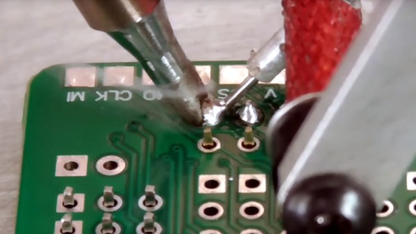
Soldering pin headers by hand is a tedious task, especially when your project has a huge number of them. [iforce2d] has a large number of boards with a lot of headers, and has created a rather special CNC machine to to do the job. It’s a soldering robot, controlled by LinuxCNC and you can see it below the break.

Superficially it resembles a 3D printer made in aluminium, with an X-Y movable table and a Z-direction represented by a soldering iron and solder feeder on an arm. The solder feeder uses a Bowden tube, with a 3D-printer extruder motor pushing the solder wire down a PTFE tube and finally into a fine aluminium tube from which it’s fed to the iron tip.

Though he’s done a beautiful job of it, creating the machine is not all that’s required, because the tool path requires more attention than simply moving the iron to each pin and supplying some solder. There’s a need to consider the effect of that heat, how much each pad needs, and how much neighbouring pads contribute.

We’ve had repetitive soldering tasks just like this one though not on this scale, so we can understand the tedium this machine will relieve. We can’t however help being reminded of XKCD 1319.

Continue reading “CNC Soldering Bot Handles Your Headers”

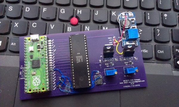
A purple PCB with a Raspberry Pi Pico and an MK3870 mask ROM microcontroller

A 1970s Mask ROM MCU Spills Its Secrets

If you buy any kind of electronic gadget today, chances are it’s powered by a microcontroller with a program stored in its internal flash ROM. That program’s code is often jealously guarded by the manufacturer, who will try their best to make sure you can’t just read back the chip’s contents by using lock bits or some sort of encryption. Things were more laid back in the 1970s and ’80s, when code was stored unencrypted in standard EPROM chips, or, for high-volume applications, in mask ROMs integrated in microcontrollers. Reading back the code of such micros was still very difficult because chips simply didn’t have a way of dumping their contents. [Andrew Menadue] ran into this issue when trying to repair an old HP calculator printer, and had to apply a clever hack to dump the contents of its Mostek MK3870 chip.

The main trick [Andrew] used was one discovered by [Sean Riddle] and explained on his website. It makes use of the fact that the MK3870 has a TEST pin that can be used to disable the mask ROM and load alternative program code directly into the micro’s processing core. By setting up a LOAD instruction pointing at a ROM location and briefly disabling test mode while that instruction is executed, the ROM’s contents can be read out by the externally loaded program.

Simple as this hack may seem, actually implementing it was tricky enough because of the strict timing requirements between signals on the clock pins, the data bus, and the TEST pin. [Andrew] got it to work on his Raspberry Pi Pico setup most of the time, but somehow the micro still returned a plainly wrong value every few hundred bytes. Not willing to spend too much time debugging this issue, [Andrew] applied a rather crude hack to his code: instead of reading each byte once, it runs the read cycle 200 times, and only returns a result when all 200 runs return the same value. Dumping the entire 4 kB of ROM now takes several minutes, but this isn’t much of an issue since [Andrew] only has one chip to read out.

If you do have a bucketload of MK3870 chips that you need to dump, you might want to try and optimize the code on [Andrew]’s GitHub page. It’s a lucky coincidence that the ‘3870 has the exploitable TEST feature; often, the only way to get inside mask ROM code is by decapping the chip and optically reading the bits one by one. Mask ROMs are great for very long term data storage, however.

Continue reading “A 1970s Mask ROM MCU Spills Its Secrets”