A couple of years ago, we covered a project called Arnis, created by [Louis Erbkamm], which allowed you to generate any portion of Earth into Minecraft blocks and maps. It was already impressive, but since we last checked in the open source project has made some incredible progress.
When we first covered Arnis, it was stuck on the Java edition of Minecraft. But now the project has been updated to support the more modern Bedrock Edition, meaning you can put your home into any device’s version of Minecraft!
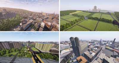
Beyond Bedrock version support, the actual tool has improved with proper elevation generation using data provided from NASA. This allows you to view the Alps or the Himalayas in all their voxel glory, or explore an entire map of the Moon. Perhaps what’s even more impressive is that the generation is accurate enough to be used in an actual research study involving flood mitigation education.
All of this has been made possible with help from a passionate community who have volunteered their time to assist [Louis] with the project — a testament to the power of open source.