Browsing the Asian marketplaces online is always an experience. Sometimes, you see things at ridiculously low prices. Other times, you see things and wonder who is buying them and why — a shrimp pillow? But sometimes, you see something that probably could have a more useful purpose than the proposed use case.
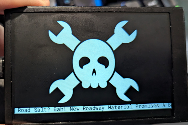
That’s the case with the glut of “smart displays” you can find at very low prices. Ostensibly, these are being sold as system monitors. A business-card-sized LCD hooks up via USB and shows your CPU speed, temperature, and so on. Of course, this requires sketchy Windows software. I don’t run Windows, and if I did, I wouldn’t be keen to put some strange service on just so I could see tiny displays of my system information. But a 3.5-inch IPS LCD screen for $15 or less probably has some other uses. But how to drive it? Turns out, it is easier than you think and the hardware looks reasonably hackable, too.
Like a lot of this cheap stuff, these screens are sold under a variety of names, and apparently, there are some subtle differences. Two of the main makers of these screens are Turing and XuanFang, although you rarely see those names in the online listings. As you might expect, though, someone has reverse-engineered the protocol, and there is Python software that will replace the stock Windows software the devices use. Even better, there is an example of using the library for your own purposes.