Join us on Wednesday, April 13 at noon Pacific for the 2022 Hackaday Prize Hack Chat with Majenta Strongheart!
Let’s face it: this world is pretty broken right now. From environmental crisis to disease and famine, shortages of just about everything, infrastructure failures, not to mention wars and social breakdown, things are getting pretty hairy out there. While it’s tempting to just curl up and pretend everything is good, that’s probably not going to work as even a short-term plan.
Luckily, we hackers are uniquely positioned for situations like this. After all, we fix stuff, and we’re certainly living in a target-rich environment of stuff that needs fixing. What’s more, nothing gives us as much fulfillment as taking a situation that everyone else thinks is beyond help and turning it into a solved problem.
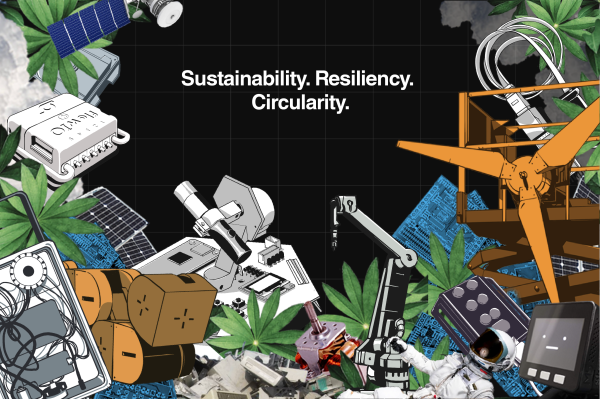
 These are the times that people like us can really shine, and the 2022 Hackaday Prize is the perfect forum for that. With this year’s theme of Sustainability, Resiliency, and Circularity, there’s plenty of scope for all of us to make a contribution. To help us get kicked off, Majenta Strongheart, Head of Design and Partnerships at Supplyframe, will drop by the Hack Chat with all the details on this year’s Prize.
Come prepared to pick her brain on how the Prize is going to work this year, find out about the different challenge opportunities, and learn everything there is to know about this year’s competition. It’s the Greatest Hardware Design Challenge on Earth, and we need it now more than ever.
Our Hack Chats are live community events in the Hackaday.io Hack Chat group messaging. This week we’ll be sitting down on Wednesday, April 13 at 12:00 PM Pacific time. If time zones have you tied up, we have a handy time zone converter.