First of all, there are definitely simpler ways to monitor remote temperatures, but [Mike]’s remote MQTT temperature sensor and display project is useful in a few ways. Not only does it lay out how to roll such a system from scratch, but it also showcases system features like solar power.
After all, if one simply wants to monitor temperature that’s easily done, but once one wishes to log those temperatures and use them to trigger other things, then rolling one’s own solution starts to get more attractive. That’s where using someone else’s project as a design reference can come in handy.
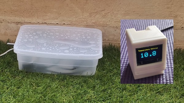
[Mike’s] solution uses two Wemos D1 boards: one with a DS18B20 temperature sensor for outdoors, and one with a small OLED screen for an interior display. The external sensor relies on a rechargeable 18650 cell and a solar panel for a hassle-free power supply, and the internal sensor (of which there can be many) has a cute enclosure and is powered by USB. On the back end, a Raspberry Pi running an MQTT gateway and Node Red takes care of the operational side of things. The whole system has been happily running for over two years.
What is MQTT? It is essentially a messaging protocol, and takes care of the whole business of reliably communicating data back and forth between IoT devices. It scales very well and doesn’t need to be hard or intimidating; our own [Elliot Williams] can tell you all about implementing it.