If you dig microcontrollers, and you like to dig into how they work, Elecia White wants to help you navigate their innermost secrets with the help of memory map files. In this refreshingly funny, but very deep keynote talk from the 2021 Hackaday Remoticon, Elecia guides us through one of the most intimidating artifacts of compilation — a file that lists where everything is being put in the microcontroller’s memory — and points out landmarks that help to make it more navigable.
And when you need to look into the map file, you probably really need to look into the map file. When your embedded widget mysteriously stops working, memory problems are some of the usual suspects. Maybe you ran out of RAM or flash storage space, maybe you have some odd hard fault and you want to know what part of the program is causing the trouble, or maybe you need to do some speed profiling to make it all run faster. In all of these cases, you get an absolute memory address. What lives there? Look it up in the memory map!
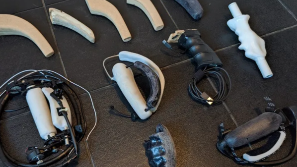
[Rob Cole] had an ambitious side project: to build an improved version of the Valve Index VR controllers. His effort, named Project Caliper, aims for optimal ergonomics and modularity for the handheld devices. [Rob] originally had plans to develop it as a consumer product by forming a small startup company, but after taking a hard look at the realities of manufacturing delays, semiconductor shortages, and the high costs of developing hardware, decided that the idea just didn’t seem justified at the time.
An XRCaliper prototype
However, the project was still to take shape. [Rob] is a self-learner, and highly passionate about the value of human-centric design. He started by building a basic controller that could be tracked in SteamVR, then a lot of work prototyping the finer points of controller design, and finally moving on to developing Project Caliper, his concept for a fully-adjustable, modular VR controller. The article he’s written takes you on a journey through the development of the project, and it is chock-full of prototype pictures for those of you who want to see just how much work can go into developing the actual physical realities of a handheld device. Some of his discoveries are pretty interesting; for example, he put a small vibration motor on a dorsal strap of one of his prototypes, thinking it would be a good place for feedback since the back of the hand is quite sensitive. It turned out that vibration applied to the back of the hand was powerfully felt as though it were inside the hand.
While its future as a consumer product isn’t certain, [Rob] is still working on the Project Caliper design and shares progress and photos on Twitter. Developing VR hardware isn’t easy, but at least there’s a much more robust framework for it nowadays, and thankfully no longer any need to roll your own tracking from scratch.
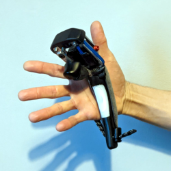
On December 5th, someone by the IRC nickname of [ubuntu] joined the Pine64 Discord’s #pinephone channel through an IRC bridge. In the spirit of December gift-giving traditions, they have presented their fellow PinePhone users with an offering – a “Snake” game. What [ubuntu] supposedly designed had the potential to become a stock, out-of-the-box-installed application with a small but dedicated community of fans, modders and speedrunners.
Unfortunately, that would not be the alternate universe we live in, and all was not well with the package being shared along with a cheerful “hei gaiz I make snake gaem here is link www2-pinephnoe-games-com-tz replace dash with dot kthxbai” announcement. Shockingly, it was a trojan! Beneath layers of Base64 and Bashfuscator we’d encounter shell code that could be in the “example usage” section of a modern-day thesaurus entry for the word “yeet“.
Tesla is well known for making cars that can accelerate quickly, but there’s always room for improvement. [Warped Perception] decided that his Tesla Model S P85D needed that little bit of extra oomph (despite the 0-60 MPH or 0-97 km/h time of 3.1 seconds), so he did what any sensible person would: add three jet turbines to the back of his car.
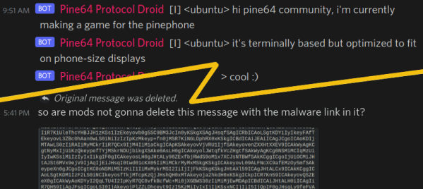
The best part of this particular build is the engineering and fabrication that made this happen. With over 200 pieces and almost all personally fabricated, this is a whirlwind of a build. The control panel is first, and there’s a particularly clever technique of 3D printing the lettering directly onto the control panel for the flat stuff. Then for the pieces with angles that would prevent the head from moving freely, he printed onto a plastic sheet in reverse, applied glue, then stuck the letters to the plate as a sheet. A top layer of clear coat ensures the letters won’t come off later.
Using a 3D printer to apply lettering on the control panel.
He installed the control electronics in the trunk with wiring strung from the car’s front to the rear. Three Arduinos serve as controllers for the jets. Afterward, came the bracket to hold the engines and attach it to the car’s underside. Unfortunately, supplies were a little hard to come by, so he had to make do with what was on hand. As a result it didn’t come out as strong as he would have hoped, but it’s still pretty impressive.
[Warped Perception] does a few tests before taking it out on the road. Then, he shifted the car into neutral and could drive the car solely on jet power, which was one of his goals. While we don’t love the idea of testing a jet engine on public roads, it certainly would discourage tailgaters.
Next, he finds a quieter road and does some speed tests. Unfortunately, it was drizzling, and the pavement was damp, putting a damper on his 0-60 standing times. Electric-only he gets 4.38 seconds, and turning on the jets plus electric shaves that down to 3.32 seconds. Overall, an incredible build that’s sure to draw a few curious glances whenever you’re out on the town.
Lithophanes are neat little artistic creations that use variations in the thickness of a material to reveal an image when lit from behind. 3D printing is a great way to make lithophanes, and they can make for beautiful Christmas decorations, too!
It’s easy to make lithophane decorations for your Christmas tree with the help of the ItsLitho tool. The online application takes any image you upload, and can generate lithophane geometry that you can 3D print at home. Print your custom bell or bauble, add the printed hooks, and then the final decoration can be backlit to reveal its image by inserting an LED from a string of Christmas lights.
The result is a beautiful, glowing decoration that displays a detailed image when lit up. All you need is a few images and a 3D printer to produce decorations as unique gifts for your family and friends.
We’ve seen the technique put to other uses too, such as in this convincing lamp designed after our very own Moon. Video after the break.
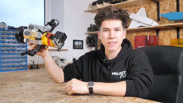
Submarines are one of the harder modes of transport to build in radio-controlled form. Doing so involves tangling with sealing electronics from water ingress and finding a way to control the thing underwater. It’s a challenge, but one relished by [Project Air] in his latest build.
The body of the sub was built from a drink bottle, serving as a stout container upon which could be mounted all the necessary hardware. Filling the bottle with water allowed buoyancy to be adjusted to a neutral level. Twin brushless motors were used for drive, while servos were waterproofed using a combination of rubber gaskets, olive oil, and sealing spray.
Control was via a floating 2.4 GHz receiver, as high-frequency radio signals don’t penetrate water very far. The floating box also carries an FPV transmitter to allow the sub to be piloted via video feed. Rather than using a ballast system, the sub instead dynamically dives by thrusting itself beneath the water’s surface.
Unfortunately, water sloshing around in the partially-filled drink bottle meant controlling the sub in pitch was virtually impossible. To fix this, [Project Air] filled the bottle completely, and then used some plugged syringes on the outside of the body to adjust buoyancy. The long heavy tether was also replaced with a much shorter one, and the sub became much more fun to drive around under water.
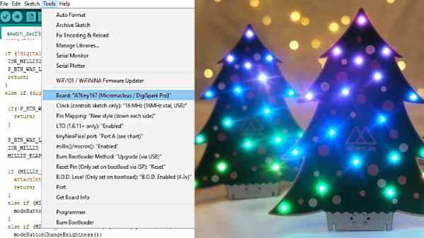
The festive season is often as good a reason as any to get out the tools and whip up a fun little project. [Simon] wanted a little tchotchke to give out for the holidays, so they whipped up a Christmas tree PCB that’s actually Arduino-compatible.
O’ Christmas Tree, on PCB…
It’s a forward-looking project, complete with USB-C connector, future-proofing it for some time until yet another connector standard comes along. When plugged in, like many similar projects, it blinks some APA102 LEDs in a festive way. The PCB joins in on the fun, with white silkscreen baubles augmented by golden ones created by gaps in the soldermask.
An ATTiny167 is the brains of the operation, using the Micronucleus bootloader in a similar configuration to the DigiSpark Pro development board. It relies on a bit-banged low-speed USB interface for programming, but the functionality is largely transparent to the end user. It can readily be programmed from within the Arduino IDE.
It’s not an advanced project by any means, but is a cute giveaway piece which can make a good impression in much the same way as a fancy PCB business card. It could also serve as an easy tool for introducing new makers to working with addressable LEDs. Meanwhile, if you’ve been cooking up your own holiday projects in the lab, don’t hesitate to drop us a line!