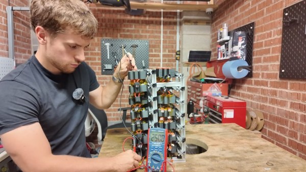
Economists have this idea that we live in an efficient market, but it’s hard to fathom that when disposable vapes are equipped with rechargeable lithium cells. Still, just as market economists point out that if you leave a dollar on the sidewalk someone will pick it up, if you leave dollars worth of lithium batteries on the sidewalk, [Chris Doel] will pick them up and build a DIY home battery bank that we really hope won’t burn down his shop.
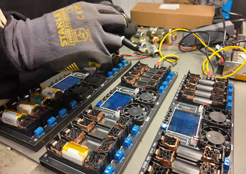
The Powerwall-like arrangement uses 500 batteries salvaged from disposable vapes. His personal quality control measure while pulling the cells from the vapes was to skip any that had been discharged past 3 V. On the other hand, we’d be conservative too if we had to live with this thing, solid brick construction or not.
That quality control was accomplished by a clever hack in and of itself: he built a device to blow through the found vapes and see if they lit up. (That starts at 3:20 in the vid.) No light? Not enough voltage. Easy. Even if you’re not building a hoe powerbank, you might take note of that hack if you’re interested in harvesting other people’s deathsticks for lithium cells. The secret ingredient was the pump from a CPAP machine. Actually, it was the only ingredient.)
In another nod to safety, he fuses every battery and the links between the 3D printed OSHA unapproved packs. The juxtoposition between janky build and careful design nods makes this hack delightful, and we really hope [Chris] doesn’t burn down his shed, because like the cut of his jib and hope to see more hacks from this lad. They likely won’t involve nicotine-soaked lithium, however, as the UK is finally banning disposable vapes.
In some ways, that’s a pity, since they’re apparently good for more than just batteries — you can host a website on some of these things. How’s that for market efficiency?
Continue reading “DIY Powerwall Blows Clouds, Competition Out Of The Water”