There’s a story that goes something like this: Chet Atkins was playing his guitar when someone remarked, ‘that guitar sounds great!’ Mr. Atkins immediately stopped playing and asked, ‘how does it sound now?’ While it’s true that the sound ultimately comes from you and your attention to expression, we feel that different pickups on the same guitar can sound, well, different from each other.
 However, this is merely speculation on our part, because changing pickups is pretty serious surgery, and there’s only one company out there making guitars with hot-swappable pickups. Since their low-end model is out of most people’s price range, [Mike Lyons] took one for the team and decided to build a guitar from scratch to test out various pickups of any size, from lipstick to humbucker. [Mike] can swap them out in under a minute, and doesn’t need any tools to do it.
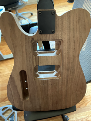
[Mike] modeled the swapping system on that one company’s way of doing things, because why reinvent the wheel? The pickups are inserted through the back and held in place with magnets and a pair of cleverly-designed printed pieces — one to mount the pickup to, and the other inside the pickup cavity.
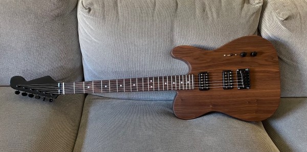
As far as actually connecting the things up, [Mike] went with a commercially-available quick-connect pickup solution that uses a mini four-conductor audio plug and jack. The body is based on the Telecaster, while the headstock is more Stratocaster — the perfect visual combination, if you ask us.
We are particularly fond of [Mike]’s list of caveats for this project, especially the requirement that it had to be built using only hand tools and a 3D printer. Although a drill press would have been nice to use, [Mike] did a fantastic job on this guitar. Whether you’re into guitars or not, this is a great story of an awesome build.
What, you don’t even have hand tools? You could just print the whole guitar instead.