Bootstrapping The Old Fashioned Way

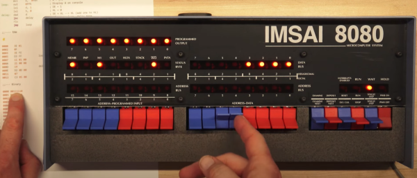
The PDP-11, the Altair 8800, and the IMSAI 8080 were some of the heroes of the computer revolution, and they have something in common — front panel switches, and a lot of them. You probably have a fuzzy idea about those switches, maybe from reading Levy’s Hackers, where the painful process of toggling in programs is briefly described. But how exactly does it work? Well thanks to [Dave Plummer] of Dave’s Garage, now we have a handy tutorial. The exact computer in question is a reproduction of the IMSAI 8080, the computer made famous by a young Matthew Broderick in Wargames. [Dave] managed to score the reproduction and a viewer saved him the time of assembly.

The example program is a Larson Scanner, AKA making an strip of lights push a pulse of light across the strip. [Dave] starts with the Assembly code, a scant 11 lines, and runs it through an assembler available online. That gives us machine code, but there’s no hex keypad for input, so we need those in 8-bit binary bytes. To actually program the machine, you set the address switches to your start-of-program location, and the data switches to your first byte. The “deposit” switch sets that byte, while the “deposit next” switch increments the address and then stores the value. It means you don’t have to key in an address for each instruction, just the data. Get to the end of the program, confirm the address is set to the start, and flick run. Hope you toggled everything in correctly. If so, you’re rewarded with a friendly scanner so reminiscent of 80s TV shows. Stick around after the break to see the demonstration!
Continue reading “Bootstrapping The Old Fashioned Way”

Upcycling Flat Scraps With Open Source Tools

If you have any sort of device that cuts like a CNC mill or a laser cutter, you probably generate a lot of strange-looking scrap material. Most of us hate to throw anything away, but how do you plan to use all these odd shapes? [Caddzeus] has an answer.  Using a camera and some software he digitizes the shapes accurately into a form usable in his CAD package of choice.

The process involves setting up some targets with known dimensions that will appear in the photograph. This allows the picture to be taken without being overly concerned about the distance to the camera or the angle.

Using GIMP, he adjusts the images to remove the perspective. He then brings the image into Inkscape where he can accurately scale and trace the shape.

There are detailed instructions — including videos — but if you know how to use these tools, you can probably figure it out for yourself. This technique would be useful, too, if you wanted to get an outline of something you intend to mill or cut into your CAD program as a reference. We like to do this with a laser cutter so you can burn the outline of something you are engraving or cutting on a piece of paper before you start and easily align the workpiece to the laser.

Of course, a small part could surrender its image to a conventional scanner and you can use a similar technique to adjust the scale. If you start using Inkscape a lot, you’ll want more plugins. You never know what you might build from some scrap odds and ends.

Continue reading “Upcycling Flat Scraps With Open Source Tools”

Troubleshooting Barcodes: A Lesson In Critical Thinking

We’ve all been there. Something that is known to work doesn’t work out in the field. But back at home base, it works fine. How do you fix it? Of course, there’s no one right answer to that question, but [Benji York] had a particularly satisfying round of troubleshooting some errant barcodes and even came up with a very creative solution.

Here’s the setup: a customer couldn’t read some barcodes sent from [Benji’s] company. Yet when the bad barcodes returned, they were fine. They looked fine, too. In a Twitter post, [Benji] challenges you to see if you can tell what’s wrong.

Continue reading “Troubleshooting Barcodes: A Lesson In Critical Thinking”

Hackaday Prize 2022: A Spring-Driven Digital Movie Camera

These days, most of us are carrying capable smartphones with high-quality cameras. It makes shooting video so easy as to take all the fun out of it. [AIRPOCKET] decided to bring that back, by converting an old spring-driven 8mm film camera to shoot digital video.

The camera in question is a magazine-fed Bell & Howell Model 172 from the 1950s. In its original spring-driven form, it could shoot for approximately 35 seconds at a (jerky) frame rate 16 fps.

In this build, though, the film is replaced with a digital imaging system designed to fit in the same space as the original magazine. A Raspberry Pi Zero 2 was pressed into service, along with a rechargeable battery and Pi camera module. The camera is timed to synchronise with the shutter mechanism via a photosensor.

Since it uses the original optics and shutter speed, the resulting video is actually very reminiscent of the Super 8 cameras of the past. It’s an impressive way to get a retro film effect straight into a digital output format. The alternative is to just shoot on film and scan it afterwards, of course! Video after the break.

Continue reading “Hackaday Prize 2022: A Spring-Driven Digital Movie Camera”

Tracing In 2D And 3D With Hall Effect Sensors

Pantographs were once used as simple mechanical devices for a range of tasks, including duplicating simple line drawings. [Tim] decided to make a modern electronic version that spits out G-Code instead.

The design relies on a 3D-printed pantograph assembly, mounted upon a board as a base. A pair of Hall effect sensors are mounted in the pantograph, which, along with a series of neodymium magnets, can be used to measure the angles of the pantograph’s joints. The Hall sensors are read by an Arduino Nano, which computes the angles into movement of the pantograph head and records it as G-Code. This can simply be displayed on the attached LCD display, or offloaded to a computer for storage.

[Tim] explains the basic theory behind the work in an earlier piece, where he built a set of electronic dividers using the same techniques. He didn’t stop there, either. He also built a more complex version that works in 3D that he calls it the Electronic Point Mapper, which can be used to generate point clouds with a 3D-capable pantograph mechanism.

It’s a neat way to learn about geometry, and could even be useful if you’re doing some work in tracing 2D drawings or measuring 3D objects.

Continue reading “Tracing In 2D And 3D With Hall Effect Sensors”

Homemade CAT Scan Shouldn’t Scan Cats

[Pyrotechnical] thought about buying a CAT scanner and found out they cost millions of dollars. So he decided to build one for about $200 using a salvage X-ray tube and some other miscellaneous parts. A scintillating detector provides the image for pick up with a camera phone. The control? An Arduino, what else? You can watch the video below, but due to plenty of NSFW language, you might want to put your headphones on if you don’t want to shock anyone.

Of course, you need to be careful when working with energetic X-rays. To keep away from the X-ray source, [Pyrotechnical] used a Roku remote and an IR sensor to control the device from afar. The electronics is pretty easy. You just have to rotate a turntable and trigger the camera while lighting up the X-ray tube.

Continue reading “Homemade CAT Scan Shouldn’t Scan Cats”

CT Scans Help Reverse Engineer Mystery Module

The degree to which computed tomography has been a boon to medical science is hard to overstate. CT scans give doctors a look inside the body that gives far more information about the spatial relationship of structures than a plain X-ray can. And as it turns out, CT scans are pretty handy for reverse engineering mystery electronic modules, too.

The fact that the mystery module in question is from Apollo-era test hardware leaves little room for surprise that [Ken Shirriff] is the person behind this fascinating little project. You’ll recall that [Ken] recently radiographically reverse engineered a pluggable module of unknown nature, using plain X-ray images taken at different angles to determine that the undocumented Motorola module was stuffed full of discrete components that formed part of a square wave to sine wave converter.

The module for this project, a flip-flop from Motorola and in the same form factor, went into an industrial CT scanner from an outfit called Lumafield, where X-rays were taken from multiple angles. The images were reassembled into a three-dimensional view by the scanner’s software, which gave a stunningly clear view of the components embedded within the module’s epoxy body. The cordwood construction method is obvious, and it’s pretty easy to tell what each component is. The transistors are obvious, as are the capacitors and diodes. The resistors were a little more subtle, though — careful examination revealed that some are carbon composition, while others are carbon film. It’s even possible to pick out which diodes are Zeners.

The CT scan data, along with some more traditional probing for component values, let [Ken] reverse engineer the whole circuit, which turned out to be a little different than a regular J-K flip-flop. Getting a non-destructive look inside feels a little like sitting alongside the engineers who originally built these things, which is pretty cool.