Ah, tiles. You can get square ones, and do a grid, or you can get fancier shapes and do something altogether more complex. By and large though, whatever pattern you choose, it will normally end up repeating on some scale or other. That is, unless you go with something like a Penrose Wave Tile. Discovered by mathematician Roger Penrose, they never exactly repeat, no matter how you lay them out.
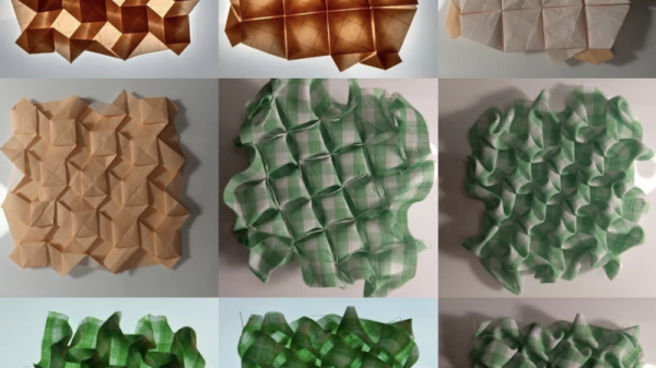
[carterhoefling14] decided to try and create Penrose tiles at home—with a 3D printer being the perfect route to do it. Creating the tiles was simple—the first step was to find a Penrose pattern image online, which could then be used as the basis to design the 3D part in Fusion 360. From there, the parts were also given an inner wave structure to add further visual interest. The tiles were then printed to create a real-world Penrose tile form.
You could certainly use these Penrose tiles as decor, though we’d make some recommendations if you’re going that path. For one, you’ll want to print them in a way that optimizes for surface quality, as post-processing is time consuming and laborious. If you’re printing in plastic, probably don’t bother using these as floor tiles, as they won’t hold up. Wall tiles, though? Go nuts, just not as a splashback or anything. Keep it decorative only.
You can learn plenty more about Penrose tiling if you please. We do love a bit of maths around these parts, too. If you’ve been making your own topological creation, don’t hesitate to drop us a line.