Logic Noise is an exploration of building raw synthesizers with CMOS logic chips. This session, we continue to abuse the 4069UB as an amplifier. We’ll turn the simple unity-gain buffer of last session into a single-pole active lowpass filter with a single part. (Spoiler: it’s a capacitor.)
While totally useful, this simple filter is a bit boring and difficult to make dynamic. So we’ll look into an entirely different filter, the Twin-T notch filter, that turns out to be sharp enough to build a sine-wave oscillator on, and tweakable enough that we’ll make a damped-oscillator drum sound out of it.
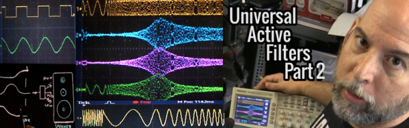
Here’s a quick demo of where we’re heading. Read on to see how we get there.
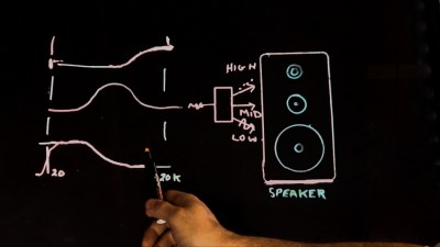
An easy way to conceptualize active filters is thinking about audio speakers. A speaker crossover has a low-pass, high-pass and band-pass effect breaking a signal into three components based upon frequency. In the previous part of this series I took that idea and applied it to a Universal Active Filter built with a single chip opamp based chip known as the UAF-42. By the way, it’s pretty much an older expensive chip, just one I picked out for demonstration.
Using a dual-ganged potentiometer, I was able to adjust the point at which frequencies are allowed to pass or be rejected. We could display this behavior by sweeping the circuit with my sweep frequency function generator which rapidly changes the frequency from low to high while we watch what can get through the filter.
In this installment I’ll test the theory that filtering out the harmonics which make up a square wave results in a predictable degradation of the waveform until at last it is a sine wave. This sine wave occurs at the fundamental frequency of the original square wave. Here’s the video but stick with me after the break to walk through each concept covered.
Today I am experimenting with a single chip Universal Active Filter, in this case I made a small PCB for the UAF-42 from Texas Instruments. I chose this part in particular as it facilitates setting the filter frequency by changing just a pair of resistors and the somewhat critical values that are contained on the chip have been laser trimmed for accuracy. This type of active filter includes Operational Amplifiers to supply gain and it supports various configurations including simultaneous operating modes such as Band Pass, Low Pass and High Pass make it “Universal”.
UAF421 Universal Active Filter
UAF421 Universal Active Filter using a dual ganged potentiometer.
Filter Basics
Speaker Crossover Example
Looking at the block diagram you can see where I have inserted a dual-ganged potentiometer to change both resistors simultaneously which should allow a straight forward adjustment for our purposes here.
Looking into the components of a simple RC filter which can easily implement a simple Low Pass or High Pass filter, we see that the math is fairly straight forward and swapping the components with each other is all that is needed to change the type of filter. Continue reading “Universal Active Filters: Part 1”→
You know what’s cool? Using your engineering knowledge to solve problems that you have while building something. This is exactly what [Reinis] did when his 3D printer’s endstop wasn’t working.
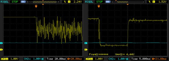
Many of us automatically go to a microcontroller when we run into a problem with a sensor, but often a simple analog filter will do the trick. The endstop in [Reinis’s] RepRap style 3D printer was giving off an unusual amount of noise when closed. When he hooked the endstop up to his oscilloscope, he was shocked to see how much noise there really was. In comes the low-pass filter. Unhappy with the response time of his low-pass filter, [Reinis] solved the problem using a pullup resistor. Two resistors and a capacitor was all that he needed to fix the problem. A great solution!
How have you used analog filters in your projects? Send us a tip and let us know!
[Udo] decided to build a clock using the DCF77 radio module seen above. This of course has been done before: the hardware draws a clock signal from the atomic clock in Braunschweig, Germany. So he grabbed a library for Arduino and got to work. But he was getting rather poor results and upon further investigation realized that the library had been written for 20 Hz modules and his operates at 300 Hz. This means better accuracy but the drawback is that the hardware is more susceptible to noise.
So began his journey to filter, process, and decode the DCF77 protocol. That link goes to the project overview. It will be in several parts all of which will be linked on that page. So far he has applied a low-pass filter and coded some exponential smoothing. He has yet to write the other four parts, but does mention that early testing shows that this technique will make the reception better than what is achieved with commercially available clocks. He was able to lock onto a signal that had more than 80% noise ratio. That’s impressive!
[Shahriar] is back with a new “The Signal Path” video. It has been a few months but it is okay because his videos are always packed full of good information. Some new equipment has been added to his lab and as an added bonus a quick tour of the equipment is included at the start, which is great if you like drooling over sweet machines.
The real focus of the video is high speed data communications, getting up into the GHz per second range. [Shahriar] covers filtering techniques from simple RC low pass filters to pretty complex microwave filters. Explaining frequency and time domain measurements of a 1.5Gbps signal through a low bandwidth channel. He also shows how equalization can be used to overcome low bandwidth limitations.
It is an hour long video jam packed with information, so you might want to set aside some time and have a pencil on hand before going in. It is well worth it though, so join us after the break.
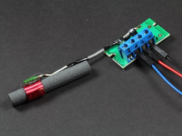
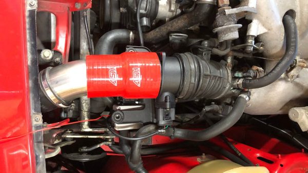
Electronic fuel injection was a big leap forward for engine control. However, early implementations often left something to be desired. This was the case for [Rob] and his Porsche 944, which had relied on an old-fashioned mechanical air flow meter (AFM). He decided to replace this with a modern mass air flow (MAF) sensor instead, and documented the process online.
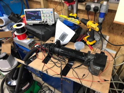
The output of the sensors was compared with a rig built using a vacuum cleaner to create air flow.
AFMs are often a target for replacement on old cars. They’re usually based on a flap that moves a potentiometer wiper across a carbon trace which wears out over the years. They can also present an air flow restriction in some cases, limiting performance. MAF sensors instead measure the amount of air flowing through with a hot wire. The amount of current required to maintain the temperature of the wire indicates the amount of air flowing through the sensor. They’re less restrictive and readily available as they’re used in many cars today.
To run a MAF in place of the AFM requires a circuit to emulate the AFM’s output. [Rob] used a STM32 Cortex-M0 to read the MAF, and then output the relevant voltage to the Porsche’s engine computer via PWM and a low pass filter. To figure out how to map the MAF’s output to match the AFM, [Rob] built a rig to blow air through both devices in series, and measuring their output on an oscilloscope. This data was used to program the STM32 to output the right emulated AFM voltage for the given MAF signal.