They say that if something is worth doing, it’s worth doing right. Those are good words to live by, but here at Hackaday we occasionally like to adhere to a slight variation of that saying: “If it’s worth doing, it’s worth overdoing”. So when we saw the incredible amount of work and careful research [Rob Linnaeus] was doing just to roast coffee beans, we knew he was onto something.
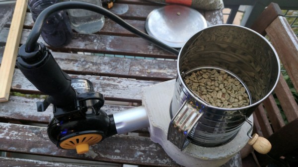
The heart of his coffee roaster is a vortex chamber with an opening on the side for a standard heat gun, and an aperture in the top where an eight cup flour sifter is to be placed. [Rob] modeled the chamber in Fusion 360 and verified its characteristics using RealFlow’s fluid simulation. He then created a negative of the chamber and printed it out on his Monoprice Maker Select 3D printer.
He filled the mold with a 1:1 mix of refractory cement and perlite, and used the back of a reciprocating saw to vibrate the mold as it set so any air bubbles would rise up to the surface. After curing for a day, [Rob] then removed the mold by heating it and peeling it away. Over the next several hours, the cast piece was fired in the oven at increasingly higher temperatures, from 200 °F all the way up to 500 °F. This part is critical, as trapped water could otherwise turn to steam and cause an explosion if the part was immediately subjected to high temperatures. If this sounds a lot like the process for making a small forge, that’s because it basically is. Continue reading “The Fine Art Of Heating And Cooling Your Beans”


 On paper, a light bulb lights up when you put current through it. In real life, it is a bit more complicated. An incandescent filament starts off as almost a dead short and draws a lot of current for a very brief time. As the current flows, the filament gets hot and the resistance goes up. That reduces the current draw. This effect — known as inrush current — is the scourge of designers trying to turn on light bulbs with transistors or other electronic switches.


