Our old algebra teacher used to say, “You have to take what you know and use it to get what you don’t know.” That saying always reminds of us sensors that convert physical quantities into things our microcontrollers can measure. Sometimes the key to a project is knowing what kind of sensor will read the physical properties of the system you are interested in. If that physical property is weight, you can use what is known as a load cell. [DegrawSt] uses four 50 kg load cells to create a bathroom scale using an Arduino.
Load cells typically contain strain gauges that change resistance when deformed. This actually measures force, but if you mount them so they measure the force exerted by you standing on a platform, you get a scale. A load cell usually has four strain gauges in a bridge configuration. This causes a voltage across the bridge, although the output can be noisy and on the order of millivolts.
When you think of who invented the induction motor, Nikola Tesla and Galileo Ferraris should come to mind. Though that could be a case of the squeaky wheel being the one that gets the grease. Those two were the ones who fought it out just when the infrastructure for these motors was being developed. Then again, Tesla played a huge part in inventing much of the technology behind that infrastructure.
Although they claimed to have invented it independently, nothing’s ever invented in a vacuum, and there was an interesting progression of both little guys and giants that came before them; Charles Babbage was surprisingly one of those giants. So let’s start at the beginning, and work our way to Tesla and Ferraris.
Water Experiment No. 33 by [Dean O’Callaghan]Most modern automata are hand-cranked kinetic sculptures typically made from wood, and [videohead118] was inspired by a video of one simulating a wave pattern from a drop of liquid. As a result, they made a 3D printed version of their own and shared the files on Thingiverse.
In this piece, a hand crank turns a bunch of cams that raise and lower a series of rings in a simulated wave pattern, apparently in response to the motion of a sphere on a central shaft. The original (shown in the animation to the right) was made from wood by a fellow named [Dean O’Callaghan], and a video of it in its entirety is embedded below the break.
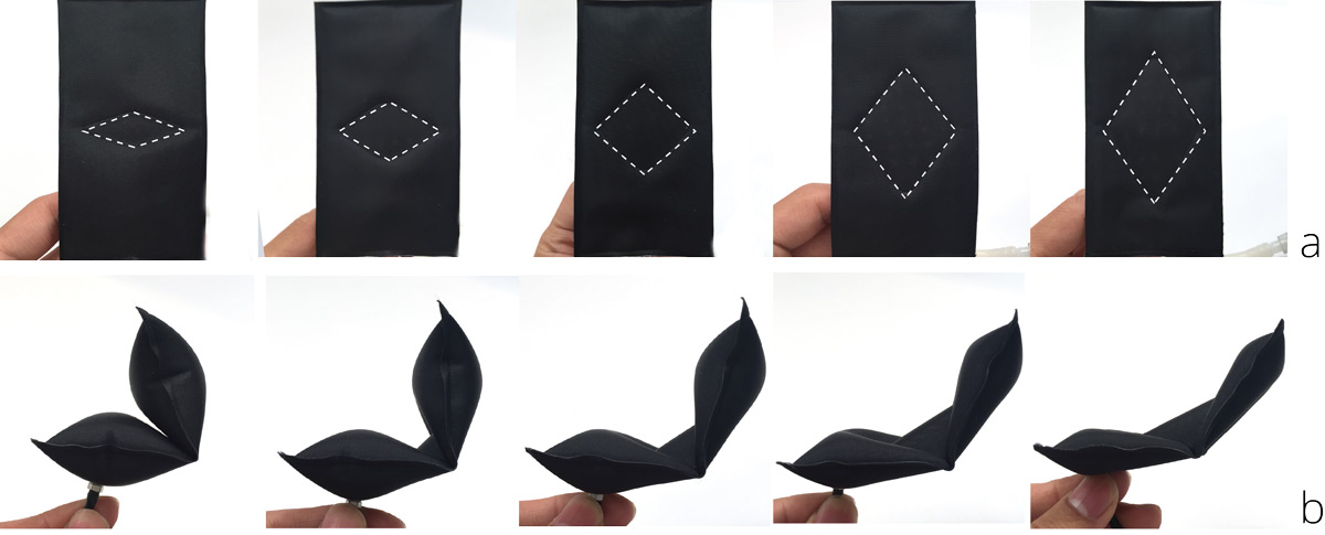
Odds are that if you’ve been to the beach or gone camping or somewhere in between, you are familiar with inflatable products like air mattresses. It’s nothing spectacular to see a rectangle inflate into a thicker, more comfortable rectangle, but what if your air mattress inflated into the shape of a crane?
We’ve seen similar ideas in quadcopters and robots using more mechanical means, but this is method uses air instead. To make this possible, the [Tangible Media Group] out of [MIT’s Media Lab] have developed aeroMorph — a program that allows the user to design inflatable constructs from paper, plastic or fabric with careful placement of a few folding joints.
These designs are exported and imprinted onto the medium by a cartesian coordinate robot using a heat-sealing attachment. Different channels allow the medium to fold in multiple directions depending on where the air is flowing, so this is a bit more complicated than, say, a bouncy castle. That, and it’s not often you see paper folding itself. Check it out!
When your publication is about to hold a major event on your side of the world, and there will be a bring-a-hack, you abruptly realise that you have to do just that. Bring a hack. With the Hackaday London Unconference in the works this was the problem I faced, and I’d run out of time to put together an amazing PCB with beautiful artwork and software-driven functionality to amuse and delight other attendees. It was time to come up with something that would gain me a few Brownie points while remaining within the time I had at my disposal alongside my Hackaday work.
Since I am a radio enthusiast at heart, I came up with the idea of a badge that the curious would identify as an FM transmitter before tuning a portable radio to the frequency on its display and listening to what it was sending. The joke would be of course that they would end up listening to a chiptune version of [Rick Astley]’s “Never gonna give you up”, so yes, it was going to be a radio Rickroll.
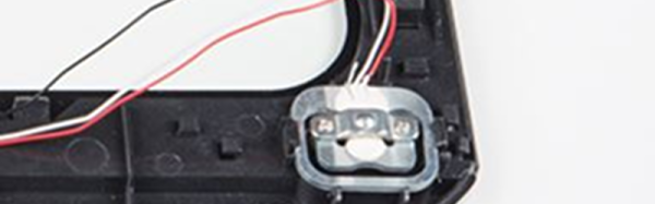
The badge internals.
I evaluated a few options, and ended up with a Raspberry Pi Zero as an MP3 player through its PWM lines, feeding through a simple RC low-pass filter into a commercial super-low-power FM transmitter module of the type you can legally use with an iPod or similar to listen on a car radio. To give it a little bit of individuality I gave the module an antenna, a fractal design made from a quarter wavelength of galvanised fence wire with a cut-off pin from a broken British mains plug as a terminal. The whole I enclosed in a surplus 8mm video cassette case with holes Dremmeled for cables, with the FM module using its own little cell and the Pi powered from a mobile phone booster battery clipped to its back. This probably gave me a transmitted field strength above what it should have been, but the power of those modules is so low that I am guessing the sin against the radio spectrum must have been minor.
At the event, a lot of people were intrigued by the badge, and a few of them were even Rickrolled by it. But for me the most interesting aspect lay not in the badge itself but in its components. First I looked at making a PCB with MP3 and radio chips, but decided against it when the budget edged towards £20 ($27). Then I looked at a Raspberry Pi running PiFM as an all-in-one solution with a little display HAT, but yet again ran out of budget. An MP3 module, Arduino clone, and display similarly became too expensive. Displays, surprisingly, are dear. So my cheapest option became a consumer FM module at £2.50 ($3.37) which already had an LCD display, and a little £5 ($6.74) computer running Linux that was far more powerful than the job in hand demanded. These economics would have been markedly different had I been manufacturing a million badges, but made a mockery of the notion that the simplest MCU and MP3 module would also be the cheapest.
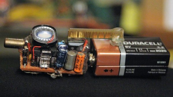
Want a little heads-up before walking into a potentially dangerous radioactive area? Sure, we all do. But the typical surplus Civil Defense Geiger counter is just too bulky to fit into the sleek, modern every-day carry of the smartphone age. So why not slim down your first line of defense against achieving mutant status with this tiny Geiger counter (Facebook)?
We jest about the use cases for a personal-sized Geiger counter, as [Ian King]’s inspiration for this miniaturized build was based more on a fascination with quantifying the unseen world around us. Details are thin in his post, but [Ian] kindly shared the backstory for this build with us. Working on a budget and mostly with spare parts, the big outlay in the BOM was $20 for a Soviet-era SBM-10 tube, itself a marvel of miniaturization. While waiting the two months needed for the tube to arrive, [Ian] whipped up a perf board circuit with a simple oscillator and a CFL transformer to provide the 400 volts needed for the tube. The whole circuit, complete with tiny speaker and an LED to indicate pulses, sits neatly on top of a 9-volt battery. The video below shows it in action with a test source.
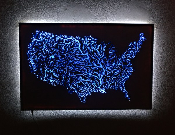
A recent convert to the ways of the laser cutter, redditor [i-made-a-thing] was in want of a project and — stumbling on some waterways maps on Etsy — launched into fabricating an illuminated map of all the waterways in the United States.
The map itself was laser-cut out of 1/4 inch plywood at his local makerspace. Thing is, smaller rivers and tributaries were too narrow at the scale [i-made-a-thing] wanted, so he ended up spending several hours in Photoshop preparing the image so larger rivers would be laser-cut — and not break off– while the rest would be etched onto the surface. After testing the process by making a few coasters, he was ready to get started on the real deal.