One of the biggest challenges of traveling to Mars is that it’s far away. That might seem obvious, but that comes with its own set of problems when compared to traveling to something relatively close like the Moon. The core issue is weight, and this becomes a big deal when you have to feed several astronauts for months or years. If food could be grown on Mars, however, this would make the trip easier to make. This is exactly the problem that [Clinton] is working on with his Martian terrarium, or “marsarium”.
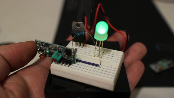
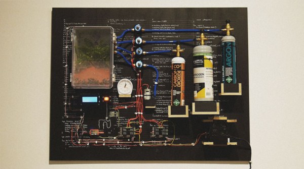
The first task was to obtain some soil that would be a good analog of Martian soil. Obtaining the real thing was out of the question, as was getting similar dirt from Hawaii. [Clinton] decided to make his own by mixing various compounds from the hardware store in the appropriate amounts. From there he turned to creating the enclosure and filling it with the appropriate atmosphere. Various gas canisters controlled by gas solenoid valves mixed up the analog to Martian atmosphere: 96% dioxide, 2% argon, and 2% nitrogen. The entire experiment was controlled by an Intel Edison with custom circuits for all of the sensors and regulating equipment. Check out the appropriately dramatic video of the process after the break.
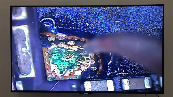
While the fern that [Clinton] planted did survive the 30-day experiment in the marsarium, it wasn’t doing too well. There’s an apparent lack of nitrogen in Martian soil which is crucial for plants to survive. Normally this is accomplished when another life form “fixes” nitrogen to the soil, but Mars probably doesn’t have any of that. Future experiments would need something that could do this for the other plants, but [Clinton] notes that he’ll need a larger marsarium for that. And, if you’re not interested in plants or Mars, there are some other interesting ramifications of nitrogen-fixing as well.