Fail Of The Week: Battery Packin’

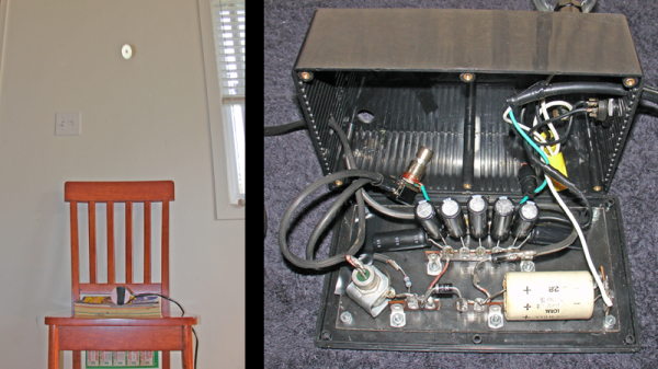
[NeXT] got himself an IBM ThinkPad TransNote and yeah, we’re pretty jealous. For the uninitiated, the TransNote was IBM’s foray into intelligent note transcription from roughly fifteen years ago. The ThinkPad doesn’t even have to be on to capture your notes because the proprietary pen has 2MB of flash memory. It won an award and everything. Not the pen, the TransNote.

Unfortunately, the battery life is poor in [NeXT]’s machine. The TransNote was (perhaps) ahead of its time. Since it didn’t last on the market very long, there isn’t a Chinese market for replacement batteries. [NeXT] decided to rebuild the replacement battery pack himself after sending it off with no luck.

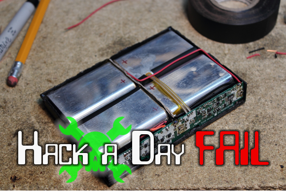
The TransNote’s battery pack uses some weird, flat Samsung 103450 cells that are both expensive and rare. [NeXT] eventually found some camera batteries that have a single cell and a charge controller. He had to rearrange the wiring because the tabs were on the same side, but ultimately, they did work. He got the cells together in the right configuration, took steps to prevent shorts, and added the TransNote’s charge controller back into the circuit.

Nothing blew up, and the ThinkPad went through POST just fine. He plugged it in to charge and waited a total of 90 minutes. The charging rate was pretty lousy, though. At 94% charge, the estimated life showed 28 minutes, which is worse than before. What are your thoughts on the outcome and if it were you, what would be the next move?


2013-09-05-Hackaday-Fail-tips-tileFail of the Week is a Hackaday column which runs every Wednesday. Help keep the fun rolling by writing about your past failures and sending us a link to the story — or sending in links to fail write ups you find in your Internet travels.

Cheap Multimeter Gauges Embedded Idle Time

How often is your microcontroller actually doing something? You can find out by measuring idle time, but how exactly do you do this? [Jack Ganssle] shows that simple embedded applications can toggle a pin when idle, which can then be measured. More complex applications like those using a Real Time Operation System can do the same by making use of the idle hook. But what can you do to make this toggling pin feedback actually mean something?

His solution is to repurpose an analog multimeter. The meter is interface with the toggle pin and a trimpot calibrates the needle. This way the needle jumps when the processor is busy and returns to zero when idle. What a great tip for getting a little more feedback about what’s going on inside of that black plastic IC package. It’s not surprising to find such a clever hack from one of the Hackaday Prize judges.

While you’re in the analog multimeter aisle you might want to pick up a couple of extras for more alternate data displays.

Continue reading “Cheap Multimeter Gauges Embedded Idle Time”

DIY Lathe DRO

Digital Caliper Sacrificed For DRO Project

In general, machining metal on a lathe or mill takes skill and patience as the accuracy of the cuts are important. To make those accurate cuts, it is important to know where the tool is located and how far it moves. For manual machines, the most basic method of determining position is by using graduated dials mounted on the hand cranks. Although these graduated dials can certainly be accurate, they may be difficult to see and they also require the operator to do math in their head on the fly with every full revolution of the dial. Another option would be a digital read out (DRO) which has an encoder mounted to the moving axes of the machine. This setup displays the exact position of the tool on an easy to read numeric display.

Professional DRO kits for mills and lathes can cost between a few hundred dollars to several thousand dollars.  [Robert] has a lathe, wanted a DRO but didn’t want to shell out serious cash to get it. He built his own for super cheap in an extremely resourceful way…. using a Harbor Freight Digital Caliper. A housing was first fabricated so that the added equipment would not hinder the axis travel of the lathe. The caliper was then cut to length, installed in the housing and the entire assembly was then mounted to the lathe.

DIY Lathe DRO
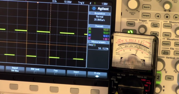
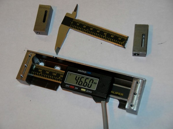
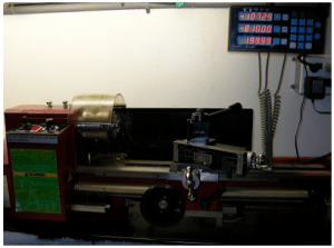
It is totally reasonable to use the stock caliper display to read the positional information, however, even these cheap digital calipers have connections for the encoder output data, which can easily be read by a microcontroller. That means it is super simple to hook these low-cost digital calipers up to a display remotely located in a more convenient position.


THP Semifinalist: A Continuous Wave Radar

There aren’t many Hackaday Prize entries playing around in RF, save for the handful of projects using off the shelf radio modules. That’s a little surprising to us, considering radio is one of the domains where garage-based tinkerers have always been very active. [Luke] is bucking the trend with a FM continuous wave radar, to be used in experiments with autonomous aircraft, altitude finding, and synthetic aperture radar imaging.

[Luke]’s radar operates around 5.8-6 GHz, and is supposed to be an introduction to microwave electronics. It’s an extremely modular system built around a few VCOs, mixers, and amplifiers from Hittite, all connected with coax.

So far, [Luke] has all his modules put together, a great pair of cans for the antennas, everything confirmed as working on his scope, and a lot of commits to his git repo.

You can check out [Luke]’s demo video is available below.


SpaceWrencher
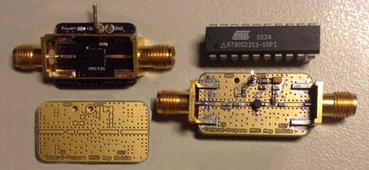
The project featured in this post is a quarterfinalist in The Hackaday Prize.

Continue reading “THP Semifinalist: A Continuous Wave Radar”

Apollo, The Everything Board

The best projects have a great story behind them, and the Apollo from Carbon Origins is no exception. A few years ago, the people at Carbon Origins were in school, working on a high power rocketry project.

Rocketry, of course, requires a ton of sensors in a very small and light package. The team built the precursor to Apollo, a board with a 9-axis IMU, GPS, temperature, pressure, humidity, light (UV and IR) sensors, WiFi, Bluetooth, SD card logging, a microphone, an OLED, and a trackball. This board understandably turned out to be really cool, and now it’s become the main focus of Carbon Origins.

There are more than a few ways to put together an ARM board with a bunch of sensors, and the Apollo is extremely well designed; all the LEDs are on PWM pins, as they should be, and there was a significant amount of time spent with thermal design. See that plated edge on the board? That’s for keeping the sensors cool.

The Apollo will eventually make its way to one of the crowdfunding sites, but we have no idea when that will happen. Carbon Origins is presenting at CES at the beginning of the year, so it’ll probably hit the Internet sometime around the beginning of next year. The retail price is expected to be somewhere around $200 – a little expensive, but not for what you’re getting.

The TinyG Motion Controller

When you go to a trade show of any kind, you’re expecting cool demos in the booths. At Maker Faire, there were plenty, but one of the most hypnotic was a robot built around Synthetos’ TinyG motion controller.

The demo was simply a large CNC gantry moving a ball bearing around on a string. The gantry moved in the X and Y axes, and the miniature wrecking ball was spooled and unspooled in the Z axis. The ball move around the space, coming to a complete stop without any swaying. There were even a few clear plastic tubes that the ball fell in, and popped out of without raising or lowering the string. It’s the height of motion controller coolness, all made possible with the TinyG.

The TinyG was one of a few motion control and CNC boards found at the faire. In its base configuration, it has 6 axes of motion control, RS485 to network several boards for crazy machine configurations, and a suitably powerful processor to do everything correctly.

DIY Electro Magnetic Pulser

EM Pulser Flings Washers, Side Effects May Include Curing Cancer Or Death

Some folks believe that exposure to electromagnetic pulses helps the human body heal itself (one portion of the [Bob Beck] protocol). [Steffan] is one of those folks and was interested in EMP generation but wasn’t crazy about the several-hundred dollar price tag for professional units. As any determined DIYer would do, he set off to make his own.

This whole thing works by straight-out-of-the-wall 110v AC running through a couple 60 watt light bulbs before moving through a rudimentary rectifier circuit. The DC output from the rectifier charges five 130uF camera flash capacitors. An inductor coil is responsible for generating the EMP and is only separated from the capacitors by a single normally-open momentary switch. Although it is possible to wrap your own coil, [Steffan] decided to use an off the shelf 2.5mH unit normally used for speaker system crossovers. Once the momentary switch is pressed, the energy in the capacitors is discharged through the inductor coil and the EMP is created. To demonstrate that the pulser does indeed work, a metal washer was placed on the inductor coil and the unit fired resulting in the washer being thrown into the air.

[Stephan] did deviate from the some of the online designs he had researched, using 7 capacitors instead of the recommended 5. The result was a firecracker-like discharge sound and melting of the 14 gauge wire. Well, back to 5 caps.