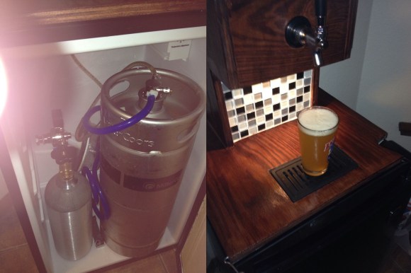
Looking for a fun weekend project? How about making your very own kegerator for about $100? Well, minus the keg of course.
First you’ll need a run of the mill mini-bar fridge. These can be had for free if you prowl student neighborhoods at the end of a semester; it’s amazing what you can find being thrown out. Next you’ll have to modify it a bit: remove the shelving and pop a hole in the top. The trickiest part is building the top out of wood, although [jypuckett] shows us that it’s really not that difficult, and wood stain is your friend!
The most expensive part of the build is probably going to be the fittings, hoses, and tap, but that’s a small price to pay for your very own kegerator.
While it’s not quite as fancy as this over-engineered kegerator, the six-tap freezer chest kegerator, or as vintage as this 1950’s General Electric fridge kegerator, it is a great example of making one for cheap, that works, and looks good.
It also raises the question: if it’s this easy to make, why haven’t you made one yet?!

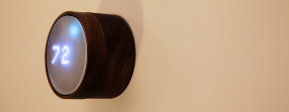 In the wake of Google’s purchase of connected devices interest Nest, the gents at [Spark]