Although to the average person a camera lens is just that bit of glass you stick on the front of the camera to make stuff appear in focus, there’s a whole wide world out there of lens designs and modifications with enough variety to make your head spin. Some of these designs make a big impact, while others fade away again, sometimes at the whims of film makers and photographers. Prism-based anamorphic lenses are an oddity that recently [Mathieu Stern] got his hands on. (Video, embedded below.)
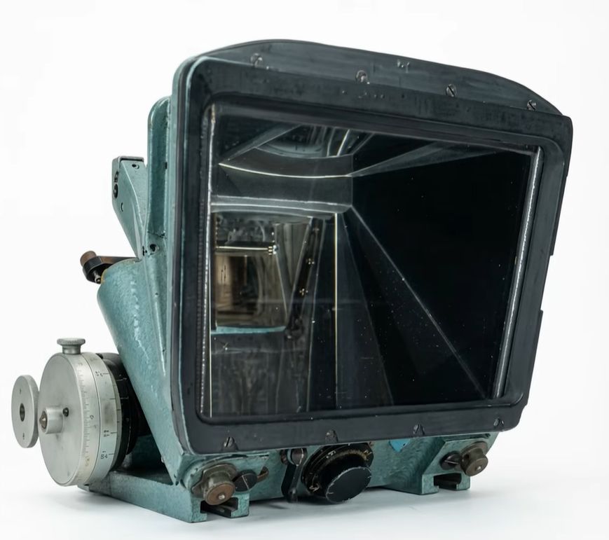
During the 1950s and 1960s there was a bit of a competition between anamorphic formats, which use special lenses that ‘squeeze’ a larger image so that widescreen movies could be recorded on standard 35 mm film. By using the same lens for recording and playback, the result was a mostly distortion-free image. Here the Technirama format by Technicolor who teamed up with Dutch company De Oude Delft (‘Old Delft’) to produce the prism-based Delrama lenses that fit on existing lenses for cameras and projectors.
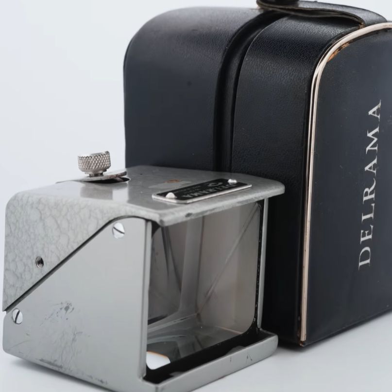
Despite having a clearly superior, distortion-free image than the cylindrical lenses of the competition, Technirama got pushed out of the commercial market, leaving De Oude Delft to try and interest the consumer market for Delrama with 8 and 16 mm adapters. These latter are the ones that [Mathieu] got his hands on and tried out with a DSLR camera.
Troublesome with these Delrama adapters is that their silver mirrors tend to degrade over time, and they also turned out to be rather fragile, which are both things that made consumers sour on them. Another challenge was the fixed four meter focus that’s great when you’re using it with a projector, but terrible for up-close shots. All of these issues resulted in Delrama fading from the market by the 1970s until all that remains are these remnants of a format that once was used to film some of the biggest Hollywood movies.
Continue reading “The Tragic Demise Of The Technirama Prism-Based Anamorphic Lens”