3D Mouse Drives Robot Arm

You’ve built the perfect robotic arm. How do you drive it? If you are [angrymop] you interface a 3D mouse from 3DConnexion via a few microcontroller boards. The Spacenavigator mouse is a staple anywhere professional CAD people are working, and it looks like it is a natural fit for a robot arm.

According to [angrymop], the Raspberry Pi can read the mouse’s commands via /dev/hidraw (that’s the raw human interface device). Each motion generates two lines of output. Each line has a unique identifying byte and values corresponding to the axis positions.

The Raspberry Pi then uses an SPI interface to talk to an ARM microcontroller and that drives the servos. The arm (the robot arm, not the processor) itself is well done, made from Lego Technic parts and common RC servos. Not that this is the most amazing thing we’ve ever seen built from Technic, but it is still pretty impressive.

You have to wonder if other 3D controllers might be useful for controlling robot arms or how the Spacenavigator would do controlling a bigger, more capable arm. Then again, maybe this arm would be the right size to build something inspired by Escher.

Continue reading “3D Mouse Drives Robot Arm”

MX3D Printing a Bridge

6-Axis Robot Arm 3D Prints A Metal Bridge

Do you remember the MX3D metal printing robot? It’s now capable of 3D printing a metal bridge. Here’s the news release, but it’s in Dutch (translated).

Over one year ago we covered the beginning of the MX3D project, which was a rather ambitious foray into 3D printing in metal with a industrial six-axis ABB robot arm. They had previously done a version using resin (MX3D Resin Printer), but then upgraded the system to use a heavy duty welding machine to deposit various metals.

One year later, they’ve tuned it even more. To show it off they printed a free form standing bridge that people can actually walk across.

Continue reading “6-Axis Robot Arm 3D Prints A Metal Bridge”

My Robot Army @ Maker Faire

For a few years now I’ve been developing an interactive army of delta robots. This ongoing project is fueled by my desire to control many mechanical extremities like an extension of my body (I’m assuming I’m not the only one who fantasizes about robots here).

IMG_1846Since my army doesn’t have a practical application… other than producing pretty light patterns and making the user feel extremely cool for a minute, I guess you’d call it art. In the past I’ve held a Kickstarter to fund the production of my art which I can now happily show at cool events with interesting people; Maker Faire being one of them.

Interactivity and Sprawling Crowds

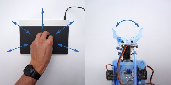
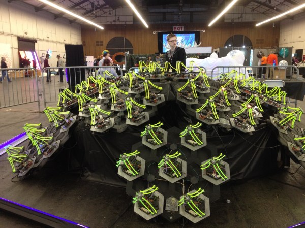
Last year, for our debut at the big Bay Area Maker Faire, my collaborator, [Mark], and I displayed a smaller sampling of 30 robots for our installation. We also decided to create an interactive aspect for others to experience. After the end of our crowdfunding period last March, we had a little over a month to do any development before the big event, so our options were slim. The easy solution was to jam our delta code into the hand tracking demo which comes with the Xbox Kinect’s Open NI within Processing. This was cool enough to exhibit, but we hadn’t really anticipated how it would go over in an environment as densely packed as the dark room at Maker Faire.

We should have known better. Both of us were aware that there would be many, many children… all with micro hands to confuse and bewilder the Kinect, but we did it anyway. Our only resolve was to implement the feature that would force the Kinect to track one hand at a time, only after being waved at in a very particular fashion. After needing to explain this stipulation to every person who stopped by our booth over the course of the weekend, we decided never to use the Kinect for crowds ever again; lesson learned.

Delta Robots and DMX

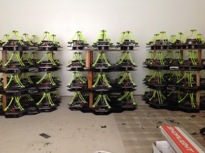
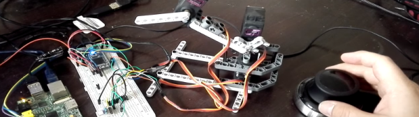
Over the past year since that experience, we’ve tripled the size of the installation and brainstormed some better demo ideas. As of now, the robots are all individually addressable over an RS485 bus, and we use the DMX protocol over a CAT5 cable to send commands. If you aren’t familiar with it, DMX is used in show production to control stage lighting… to which there is a super neat and free application called QLC+ that allows you to effectively orchestrate the motion and color of many individual light units; perfect for our cause.

qlcDeltasFunctionally, each of the 84 delta robots in the installation believes that it is a stage light (robots with identity issues). We mapped the X and Y axis of the end effector to the existing pan and tilt values, and the z axis to the beam focus value. The RGB of the LED mounted in the end effector of each delta maps directly to the RGB value of the stage light.

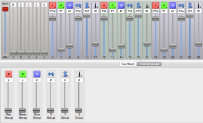
By using the sliders in the QLC+ GUI, I could select groups of robots and create presets for position and color. This was great, someone like me who doesn’t really write a lot of code could whip up impressive choreography with little sweat. Additionally, the program comes with a nice visualizer, where you can layout virtual nodes and view your effects as you develop them.

This is the layout of our installation mapped in QLC+. The teal and purple sliders around each light represent pan and tilt (or in our case X and Y):

QLCdelta

Lighting control was an interesting solution. Having autonomous robots this year changed how people responded to them, as they were less like an army you’d command and more of a hypnotic field of glowing grass.

[Mark] and I are considering picking up some flex sensors and maybe playing with the Leap or an EEG headset as a means to reintroduce the interactive aspect. Bottom line, I have this cool new toy that I can’t wait to play with over the summer!

Continue reading “My Robot Army @ Maker Faire”

robot arm laser cutter

Robot Arm Wields Laser, Cares Not For Your Safety

Here at Hackaday we’ve covered a bunch of DIY laser diode projects. And for good reason, they are just cool. We’ve seen people add lasers to their 3D printers, stick one in a milling machine, use a highly modified scanner and even build a simple XY gantry specifically for the task. To say the least there is definitely a wide range of methods for moving around a laser but we’ve never seen anything like what [Sp4rky] sent in to us. He and his friends outfitted an old educational robot arm with a laser.

The robot arm is a 5 axis Armdroid 5100 picked up from eBay for a couple hundred dollars. It didn’t come with a controller but all of the stepper drivers were housed in the base of the arm. After a little tinkering around with the inputs the team was able to get the arm to move by sending serial commands from a PC, through an Arduino Mega which then sends the appropriate signals to the uni-polar stepper drivers. That was the easy part of the build.

The hard part was getting the arm to hold the laser at a consistent angle and height above the table. Inverse Kinematics to the rescue! Since the desired position of the laser, as well as the length of the arm segments is known, mathematical formulas can be derived to determine the necessary arm segment and joint positions while moving the laser around. The process flow starts out with an image in Inkscape, g-code is then generated with this plugin, then sent to the Arduino running a modified version of GRBL that has the inverse kinematic formulas. The Arduino directly controls the stepper drivers and the robotic arm moves. The Arduino also controls 3 constant-current laser drivers made from LM317 regulators. Three laser drivers, why?

Triple Laser Robot
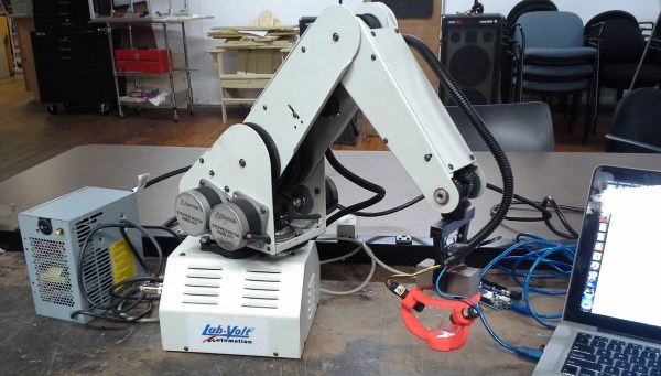
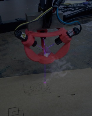
[Sp4rky] got his laser diode modules out of surplus medical equipment and, unfortunately, the rated optical wattage was quite low. Since he had 3 diodes, he decided to try to combine the 3 low power beams into one high power beam. This can be done using a prism. A prism splits sunlight into a rainbow of colors because each wavelength(color) of light that passes through the prism is bent a different amount. Since the laser diodes only put out one wavelength of light, the beam bends but does not split or diffuse. A 3D printed bracket points each laser diode at a 3-sided pyramidal prism which sends the combined beam of light straight out the bottom towards the object to be cut or engraved.

This project is cool enough that we would have covered it even if [Sp4rky] wasn’t burning a Hackaday logo. Although it doesn’t hurt for anyone wanting their project to get covered!

A Recycled Robot Arm For All!

It’s mind boggling how much e-waste we throw out. Perfectly good components, mass produced for pennies. And at the end of their life, going straight to a landfill or some poor country to be melted down. Don’t you wish you could help?

Stepper motors are a dime a dozen when it comes to e-waste, and there’s tons of cool projects you can do with a stepper motor — [Madivak] is just starting on a robot arm design over at Hackaday.io that makes use of recycled components.

It’s fairly early in development, but that means it’s a great time to start following it on the project site. The robotic arm is being designed for his final year project in his undergrad degree. Besides the steppers, he’s using his school’s Utilimaker 3D printer to manufacture all of the other mechanical components with control coming from DRV8825 stepper drivers and the Freescale Freedom KL25Z dev kit. Check out the clips after the break to see current state of the build.

Continue reading “A Recycled Robot Arm For All!”

Hacklet 30 – Robot Arm Projects

Robot arms – they do everything from moving silicon wafers to welding cars. Many a hacker has dreamt of having their own robot arm to serve them beer help them build projects. This week’s Hacklet features some of the best robot arm projects on Hackaday.io!

robotarm1We start with [4ndreas] who is building this incredible 3D Printable Robot Arm. Inspired by large industrial robots, [4ndreas] has given us an entirely 3D printable design. [4ndreas’] 3D design experience really shows here. This arm looks like it just finished work at a local assembly line! The arm is BIG too – printing the parts took him about a week, and used around 1.2kg of ABS filament! [4ndreas] has recently split the project off into two halves: his blue arm is driven by stepper motors, while the orange arm is a DC motor affair. Both of the arms can use his awesome gripper design. Check out the project page for videos of the arm in action!

6dofarmNext up is [Dan Royer] and his 6DOF Robot Arm. [Dan’s] didn’t want to spend upwards of $10,000 on an industrial arm, so he built his own from wood, plastic, and easily obtainable parts. As the name implies, the arm has 6 degrees of freedom. The electronics consist of beefy NEMA 17 stepper motors and a RUMBA controller, which was originally designed for 3D printers. Dan even created some novel encoder mounts. Each joint has an encoder, which will allow the robot to run as a closed loop system. [Dan] originally entered this arm in The Hackaday Prize 2014. While it didn’t get him to space, we’re betting it will be able to get him a soda!

MeArm

No robot arm Hacklet would be complete without featuring [ben.phenoptix] and the awesome MeArm. MeArm is a pocket-sized robot arm which uses tiny 9 gram servos for locomotion. It’s built from laser cut acrylic and standard hardware. We loved the MeArm so much that we featured it as one of the challenges in our Embedded Hardware Workshop in Munich. More recently, [Ben] and MeArm have had a great run on Kickstarter. Let’s hope those arms are good at stuffing, addressing, and mailing out packages!


owiFinally we have [Kenji Larsen] with Reactron material transporter. The material transporter is just a small part of [Kenji’s] larger Reactron project. It started with an OWI-535 robot arm. The OWI is really a toy – a plastic kit which builds an open loop DC motor driven arm. [Kenji] has put some serious time into modifying his particular arm. He experimented with molding his own potentiometers for each joint before settling on a printed circuit board based design. Once the new system was in place, he found that his resistors were good for about 10,000 cycles. Not bad for a modified toy!

There are quite a few robot arm projects we weren’t able to cover in this edition of The Hacklet – you can check them all out on our brand new Robot Arm Projects List!

That’s it for this Hacklet, As always, see you next week. Same hack time, same hack channel, bringing you the best of Hackaday.io!

DIY Robot Arm

Robot Arm You Can Build At Home

[jjshortcut] has created an easy to make robot arm that has 6 degrees of freedom. There is not much to it, the frame is made out of 4mm thick hardboard, hobby servos provide the power and a handful of hardware holds it together. The frame has been successfully cut out on both a laser cutter and a cnc router, making this design even more obtainable for any aspiring roboticist.

To control the robot arms movements [jjshortcut] plans to use a standard Arduino. There are certainly plenty of servo motor shields available but he still decided to design his own. In addition to the standard motor power and servo connections, a header for an infrared receiver was added for potential future communication options.

DIY Robot Arm GripperLike any project, there were some hiccups along the way. First, several revisions of the gripper were necessary to get the correct tooth profile that resulted in smooth and tight movement. Also, while making the shield the spacing between banks of headers came out one header too close! On this first board [jjshortcut] just bent the pins so they would fit into the Arduino. You can’t let some minor snafu prevent forward momentum of a project!

[jjshortcut] has done the hard part; the design. He has made all his mechanical and electronic files available… so go and build one! Check out the video after the break.

Continue reading “Robot Arm You Can Build At Home”