Home automation with high usefulness and low annoyance tends to rely on reliable person sensing, and [francescopace]’s ESPectre shows one way to do that cheaply and easily by leveraging hardware that’s already present on a common dev board.
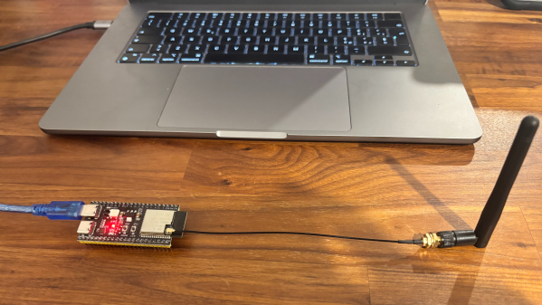
 ESPectre is an ESP32-based open source motion detector that detects movement without any cameras or microphones. It works similarly to millimeter-wave (mmWave) radar motion detectors in the sense that when a person moves, wireless signals are altered slightly as a result. ESPectre can detect this disturbance by watching and analyzing the Wi-Fi channel state information (CSI) and doing some very smart math and filtering. It’s cheap, easy to deploy and use, and even integrates with Home Assistant.
Combining a sensor like this with something else like a passive infrared (PIR) motion sensor is one way to get really robust results. But keep in mind that PIR only senses what it can see, whereas ESPectre works on WiFi, which can penetrate walls.
Since ESPectre supports low-cost ESP32 variants and is so simple to get up and running, it might be worth your time to give it a trial run. There’s even a browser-based ghost-dodging game [francescopace] put online that uses an ESPectre board plugged in over USB, which seems like a fun way to get a feel for what it can do.