Raspberry Pi RP2040: Hands-On Experiences From An STM32 Perspective

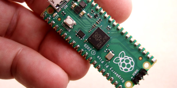
The release of the Raspberry Pi Foundation’s Raspberry Pi Pico board with RP2040 microcontroller has made big waves these past months in the maker community. Many have demonstrated how especially the two Programmable I/O (PIO) state machine peripherals can be used to create DVI video generators and other digital peripherals.

Alongside this excitement, it raises the question of whether any of this will cause any major upheaval for those of us using STM32, SAM and other Cortex-M based MCUs. Would the RP2040 perhaps be a valid option for some of our projects? With the RP2040 being a dual Cortex-M0+ processor MCU, it seems only fair to put it toe to toe with the offerings from one of the current heavyweights in the 32-bit ARM MCU space: ST Microelectronics.

Did the Raspberry Pi Foundation pipsqueak manage to show ST’s engineers how it’s done, or should the former revisit some of their assumptions? And just how hard is it going to be to port low-level code from STM32 to RP2040? Continue reading “Raspberry Pi RP2040: Hands-On Experiences From An STM32 Perspective”

DIY I2C Tester

[Dilshan] built a dedicated I2C tester which allows for I2C bus control over USB using simple commands such as init, read, write, etc. The Linux kernel has had I2C driver support for a couple of decades, but you’ll be hard pressed to find a computer or laptop with a I2C connector (excluding Bunnie Huang’s Novena hacker’s laptop, of course). This tester does require a Linux host, and his programs use libusb on the computer side and V-USB on the embedded side.

[Dilshan] put a lot of time into building this project, and it shows in the build quality and thorough documentation. With its single-sided PCB and all thru-hole construction, it makes a great beginner project for someone just getting into the hobby. At the heart of the tester is an ATmega16A in a 40-pin PDIP package (despite the Microchip overview page calling it a 44-pin chip), supported by a handful of resistors and transistors. Schematics are prepared in KiCad, code is compiled using gcc and avr-gcc, and he provides a label for the enclosure top. The only thing missing is information on the enclosure itself, but we suspect you can track that down with a little sleuthing (or asking [Dilshan] himself).

If you use I2C quite a lot, give this project a look. Easy to build, useful in the lab, and it looks nice as well. We have featured [Dilshan]’s work over the years, including this logic pattern generator and his two-transistor-on-a-breadboard superheterodyne receiver.

Free RTOS

Getting Started With FreeRTOS And ChibiOS

If operating systems weren’t so useful, we would not be running them on every single of our desktop systems. In the same vein, embedded operating systems provide similar functionality as these desktop OSes, while targeting a more specialized market. Some of these are adapted versions of desktop OSes (e.g. Yocto Linux), whereas others are built up from the ground up for embedded applications, like VxWorks and QNX. Few of those OSes can run on a microcontroller (MCU), however. When you need to run an OS on something like an 8-bit AVR or 32-bit Cortex-M MCU, you need something smaller.

Something like ChibiOS (‘Chibi’ meaning ‘small’ in Japanese), or FreeRTOS (here no points for originality). Perhaps more accurately, FreeRTOS could be summarized as a multi-threading framework targeting low-powered systems, whereas ChibiOS is more of a full-featured OS, including a hardware abstraction layer (HAL) and other niceties.

In this article we’ll take a more in-depth look at these two OSes, to see what benefits they bring. Continue reading “Getting Started With FreeRTOS And ChibiOS”

Ask Hackaday: What’s Your Favourite Build Tool? Can Make Ever Be Usurped?

What do you do whilst your code’s compiling? Pull up Hackaday? Check Elon Musk’s net worth? Research the price of a faster PC? Or do you wonder what’s taking so long, and decide to switch out your build system?

Clamber aboard for some musings on Makefiles, monopolies, and the magic of Ninja. I want to hear what you use to build your software. Should we still be using make in 2021? Jump into the fray in the comments.

Continue reading “Ask Hackaday: What’s Your Favourite Build Tool? Can Make Ever Be Usurped?”

Free RTOS

Real-Time OS Basics: Picking The Right RTOS When You Need One

When do you need to use a real-time operating system (RTOS) for an embedded project? What does it bring to the table, and what are the costs? Fortunately there are strict technical definitions, which can also help one figure out whether an RTOS is the right choice for a project.

The “real-time” part of the name namely covers the basic premise of an RTOS: the guarantee that certain types of operations will complete within a predefined, deterministic time span. Within “real time” we find distinct categories: hard, firm, and soft real-time, with increasingly less severe penalties for missing the deadline. As an example of a hard real-time scenario, imagine a system where the embedded controller has to respond to incoming sensor data within a specific timespan. If the consequence of missing such a deadline will break downstream components of the system, figuratively or literally, the deadline is hard.

In comparison soft real-time would be the kind of operation where it would be great if the controller responded within this timespan, but if it takes a bit longer, it would be totally fine, too. Some operating systems are capable of hard real-time, whereas others are not. This is mostly a factor of their fundamental design, especially the scheduler.

In this article we’ll take a look at a variety of operating systems, to see where they fit into these definitions, and when you’d want to use them in a project. Continue reading “Real-Time OS Basics: Picking The Right RTOS When You Need One”

Motor Controller Reverse Engineering Releases Smoke

It may have been designed for a sewing machine, but [Haris Andrianakis] found his imported DC brushed motor was more than up to the challenge of powering his mini lathe. Of course there’s always room for improvement, so he set out to reverse engineer the motor’s controller to implement a few tweaks he had in mind. Unfortunately, things took an unexpected turn when plugging his AVR programmer into the board’s ISP socket not only released the dreaded Magic Smoke, but actually tripped the breaker and plunged his bench into darkness.

Studying how the Hall-effect sensors in the motor are wired.

Upon closer inspection, it turned out the board has no isolation between the high voltage side and its digital logic. When [Haris] connected his computer to it via the programmer, the 330 VDC coming from the controller’s rectifier shorted through the USB bus and tripped the Earth-leakage circuit breaker (ELCB). The good news is that his computer survived the ordeal, and even the board itself seemed intact. But the shock must have been too much for the microcontroller he was attempting to interface with, as the controller no longer functioned.

Now fully committed, [Haris] started mapping out the rest of the controller section by section. In the write-up on his blog, he visually masks off the various areas of the PCB so readers have an easier time following along and understanding how the schematics relate to the physical board. It’s a nice touch, and a trick worth keeping in mind during your own reverse engineering adventures.

In the end, [Haris] seems to have a good handle on what the majority of the components are up to on the board. Which is good, since getting it working again now means replacing the MCU and writing new firmware from scratch. Or perhaps he’ll just take the lessons learned from this controller and spin up his own custom hardware. In either event, we’ll be keeping an eye out for his next post on the subject.

The Mystery Of A Particular ATtiny85 Fuse

First-timers playing with 8-bit micros such as the AVR and PIC will at some point in their lives, find themselves locked out of their MCUs. This is usually attributed to badly configured fuses that disable certain IO functions rending the device unprogrammable via conventional ICSP methods. [Uri Shaked] shares his story of how his ATtiny85 got locked and became the subject of a lengthy investigation into fuse bit configurations.

[Uri]’s journey started when he accidentally left some pins of the device connected to a second board while he was flashing the firmware. He quickly researched online for a solution for the problem and it turns out, there are a number of recipes to resolve the issue. As it turns out, his problem was not so straight-forward and warranted more digging. [Uri] ended setting up a High Voltage Programming serial programming setup and then probing the communications. He discovered that the chip refused to reset its fuses and would reject attempts to set fuses.

Further investigation of the fuse bits and reading them proved useful in understanding that the memory protection features were preventing alteration of the device. The quick-fix was to erase the ATtiny and things were back to normal thereafter. [Uri] details his pursuit of reading and comparing fuse bits from the impacted chip against a fresh device which is where he makes the discovery. The write-up is a case study in the investigation into the idiosyncrasies of device programming and will be a great resource for many and reduce hair loss for some.

Once you get your hands on an ATTINY, there are a number of small experiments to be done to cure boredom. Be sure to share your experiments and stories with us to inspire the masses.