Virtual Mini Pinball Cabinet Scores Big

Do you love pinball, but can’t justify owning a full-size cabinet? Yeah, us either, and that’s why we’re so interested in [mircemk]’s great-looking DIY mini virtual pinball cabinet. Since [mircemk] is a IT service specialist, they are lucky enough to have access to lots used and broken equipment, and that’s what this build is made of.
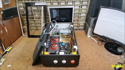
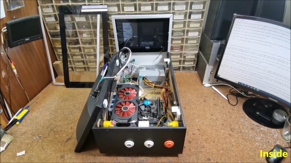
Essentially two computers working together, the playfield is a old 17-inch monitor that needed its LED lighting replaced before gracing the MDF cabinet The backglass is an ancient 10-inch tablet that was perfect for this application.

Even the motherboard, RAM, and SSD came from one of [mircemk]’s previous PCs. The SSD needed some attention first as well — it didn’t work sometimes, and didn’t show up in the BIOS at all, so [mircemk] threw it in the oven for 10 minutes at 250°, and now all is well.

One thing we really like about this build is that instead of designing a control board for the buttons, [mircemk] used a cheap USB joystick and wired them up to the pads.

So how does the tablet figure into all of this? It’s connected to a PC via USB and does its job thanks to a piece of software called Wired XDisplay. There is even a tilt switch in this bad boy. Because what’s a pinball cabinet without a tilt switch? A cheater’s cabinet, that’s what. Check out the build/demo video after the break.

Don’t even have the space for a mini cabinet? We hear you. Here’s one that fits in the palm of your hand.

Continue reading “Virtual Mini Pinball Cabinet Scores Big”

Blaupunkt Tube Radio Is The Sultan Of Radios

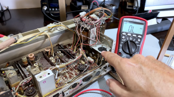
According to [M Caldeira], the Blaupunkt Sultan 24300 was one of the last tube radios made in the 1960s. He’s got one but it needed some tender loving care, and you can see how he approaches a restoration like this in the video below.

The radio was actually in better shape physically than most of the old radios we see. It wasn’t perfect, but it looked good on the outside. Electrically, though, it did need some work, and the dial had problems, too. The first obstacle was identifying exactly the model of the radio since there were a number of Sultan radios produced.

Continue reading “Blaupunkt Tube Radio Is The Sultan Of Radios”

Marionette 3D Printer Replaces Linear Rails With String

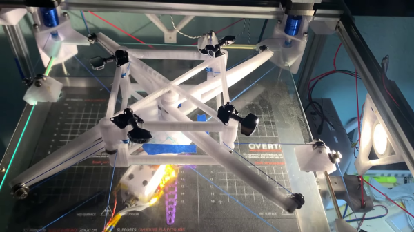
In the early days of FDM 3D printing, the RepRap project spawned all sorts of weird and and wonderful designs. In the video after the break [dizekat] gives us a throwback to those times with the Marionette 3D printer, completely forgoing linear rails in favor of strings.

The closest thing to a linear guide found on the Marionette is a pane of glass against which the top surface of the print head slides. A pair of stepper motors drive the printhead in the XY-plane, similar in concept to the Maslow CNC router, but in this case two more strings are required to keep the mechanism in tension. To correctly adjust the length of the string across the full range of motion, [dizekat] uses a complex articulating pulley mechanism that we haven’t seen before. The strings are also angled slightly downward from the spool to the print head, holding it in place against the glass.

The bed print bed is also suspended and constrained using string, with no rigid mechanical member attaching it to the frame of the printer. Six strings connected to the sides and bottom of the bed frame constrain it in 6-DOF, and pass through another pulley arrangement to three more strings and finally to a single stepper driven belt.

We can’t see any particular advantage to forgoing the linear rails, especially when the mechanisms have to be this complex, but it certainly make for an interesting engineering challenge. Whatever the reason, the end result is fascinating to watch move, and the print quality even looks decent.

Continue reading “Marionette 3D Printer Replaces Linear Rails With String”

Polish Up Your Product With Graphic Overlays

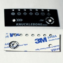
[Kevin Hunckler] recently did some in-house manufacturing for a product and shared his experiences in adding high-quality custom graphic overlays or acrylic panels to give the finished units a professional look. The results look great and were easy to apply, making his product more attractive without needing much assembly work.

A graphic overlay with transparent areas, a cutout, and adhesive backing to fit an off-the-shelf Hammond enclosure.

Sadly, when doing initial research he was disappointed to find very little information on the whole process. While in the end it isn’t terribly complex, it still involved a lot of trial and error before he zeroed in on what the suppliers in the industry expect. Fortunately, everything can be done with tools most hackers probably already have access to.

The process seems to us somewhat reminiscent of having PCBs manufactured. One defines the product housing, outlines the overlay, creates the artwork, defines an adhesive layer, and makes a design document explaining each layer and important feature. [Kevin] provides examples of his work, one of which fits an off-the-shelf Hammond enclosure.

Professionally-made acrylic panels or graphic overlays is something worth keeping in mind for hobbyists and those who might engage in desktop manufacturing, as long as the costs are acceptable. Rather like PCBs, costs go down as quantities go up. [Kevin]’s 50 mm x 50 mm overlay cost about 1 USD each in quantity 200, but only 0.50 USD each when buying 500.

These may be great for low or middling quantities, but that doesn’t mean one is out of options for prototypes or micro quantities. We have seen fantastic results adding full-color images to 3D prints, and even using a 3D printer to draw labels directly onto prints.

Designing A Macintosh-to-VGA Adapter With An LM1881

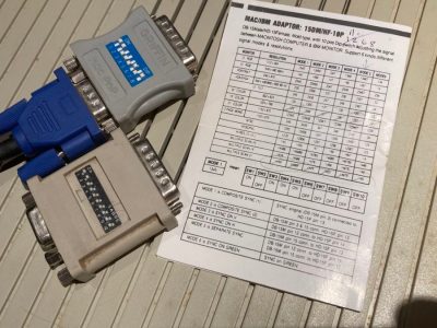
Old-school Macintosh-to-VGA adapter. Just solve for X, set the right DIP switches and you’re golden.

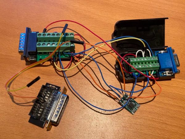
If you’re the happy owner of a vintage Apple system like a 1989 Macintosh IIci you may know the pain of keeping working monitors around. Unless it’s a genuine Apple-approved CRT with the proprietary DA-15-based video connector, you are going to need at least an adapter studded with DIP switches to connect it to other monitors. Yet as [Steve] recently found out, the Macintosh’s rather selective use of video synchronization signals causes quite a headache when you try to hook up a range of VGA-equipped LCD monitors. A possible solution? Extracting the sync signal using a Texas Instruments LM1881 video sync separator chip.

Much of this trouble comes from the way that these old Apple systems output the analog video signal, which goes far beyond the physical differences of the DA-15 versus the standard DE-15 D-subminiature connectors. Whereas the VGA standard defines the RGB signals along with a VSYNC and HSYNC signal, the Apple version can generate HSYNC, VSYC, but also CSYNC (composite sync). Which sync signal is generated depends on what value the system reads on the three sense pins on the DA-15 connector, as a kind of crude monitor ID.

Theoretically this should be easy to adapt to, you might think, but the curveball Apple throws here is that for the monitor ID that outputs both VSYNC and HSYNC you are limited to a fixed resolution of 640 x 870, which is not the desired 640 x 480. The obvious solution is then to target the one monitor configuration with this output resolution, and extract the CSYNC (and sync-on-green) signal which it outputs, so that it can be fudged into a more VGA-like sync signal. Incidentally, it seems that [Steve]’s older Dell 2001FP LCD monitor does support sync-on-green and CSYNC, whereas newer LCD monitors no longer list this as a feature, which is why now more than a passive adapter is needed.

Although still a work-in-progress, so far [Steve] has managed to get an image on a number of these newer LCDs by using the LM1881 to extract CSYNC and obtain a VSYNC signal this way, while using the CSYNC as a sloppy HSYNC alternative. Other ICs also can generate an HSYNC signal from CSYNC, but those cost a bit more than the ~USD$3 LM1881.

Sine-wave Speech Demonstrates An Auditory One-way Door

Sine-wave speech can be thought of as a sort of auditory illusion, a sensory edge case in which one’s experience has a clear “before” and “after” moment, like going through a one-way door.

Sine-wave speech (SWS) is intentionally-degraded audio. Here are the samples, and here’s what to do:

  1. Choose a sample and listen to the sine-wave speech version (SWS). Most people will perceive an unintelligible mix of tones and beeps.
  2. Listen to the original version of the sentence.
  3. Now listen to the SWS version again.

Most people will hear only some tones and beeps when first listening to sine-wave speech. But after hearing the original version once, the SWS version suddenly becomes intelligible (albeit degraded-sounding).

These samples were originally part of research by [Chris Darwin] into speech perception, but the curious way in which one’s experience of a SWS sample can change is pretty interesting. The idea is that upon listening to the original sample, the brain — fantastic prediction and learning engine that it is — now knows better what to expect, and applies that without the listener being consciously aware. In fact, if one listens to enough different SWS samples, one begins to gain the ability to understand the SWS versions without having to be exposed to the originals. In his recent book The Experience Machine: How Our Minds Predict and Shape Reality, Andy Clark discusses how this process may be similar to how humans gain fluency in a new language, perceiving things like pauses and breaks and word forms that are unintelligible to a novice.

This is in some ways similar to the “Green Needle / Brainstorm” phenomenon, in which a viewer hears a voice saying either “green needle” or “brainstorm” depending on which word they are primed to hear. We’ve also previously seen other auditory strangeness in which the brain perceives ever-increasing tempo in music that isn’t actually there (the Accelerando Illusion, about halfway down the list in this post.)

Curious about the technical details behind sine-wave speech, and how it was generated? We sure hope so, because we can point you to details on SWS as well as to the (free) Praat software that [Chris] used to generate his samples, and the Praat script he wrote to actually create them.

Implementing Commodore’s IEC Bus Protocol On A KIM-1 Single Board Computer

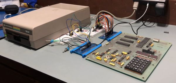
Although the PET is most likely the more well-known of Commodore’s early computer systems, the KIM-1 (Keyboard Input Monitor) single board computer was launched a year prior, in 1976. It featured not only the same MOS 6502 MPU as later Commodore systems, but also an MCS6530 PIO IC that contained the ROM, RAM and programmable I/O, reminiscent of later I/O chips on Commodore systems. As the KIM-1 was only designed to be used with an external tape drive (and a terminal for fancy users), adding a floppy drive like the ubiquitous 1541 with its IEC bus interface was not a first-party accessory. How the IEC bus can be retrofitted to a KIM-1 system is demonstrated in this video by the Commodore History channel.

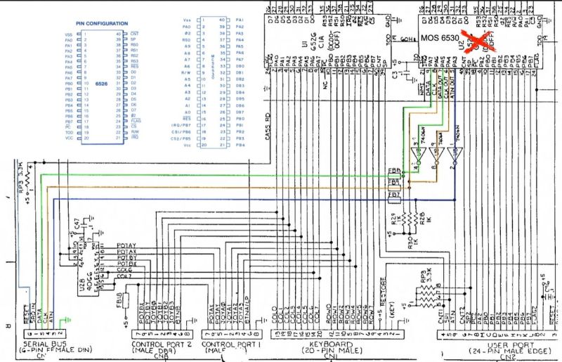
The Commodore KIM-1 hardware is almost directly compatible with the C64 hardware. (Credit: Commodore History on YouTube)

What is most notable is just how similar the KIM-1 hardware is to later PET and VIC hardware, with the CIA and PIO ICs featuring the same requisite pins for this purpose, and requiring only the addition of an inverting (SN7406) IC and an EPROM featuring the new code to support the proprietary Commodore IEC bus protocol, which was mostly pilfered byte-for-byte from a C64 kernal ROM.

With some creative breadboarding in place and using nothing more than the on-board LED display and keyboard matrix, it was then possible to write to the inserted floppy disk, and also to read back from it. What’s interesting here is that this essentially replaces the tape drive as target for the KIM-1, which thus retains a lot of the original functionality, but with a big performance boost. While perhaps only interesting as an academic exercise, it’s definitely an interesting look at the early beginnings of what would blossom into the Commodore 64.

Continue reading “Implementing Commodore’s IEC Bus Protocol On A KIM-1 Single Board Computer”