Designing A Macintosh-to-VGA Adapter With An LM1881

Old-school Macintosh-to-VGA adapter. Just solve for X, set the right DIP switches and you’re golden.

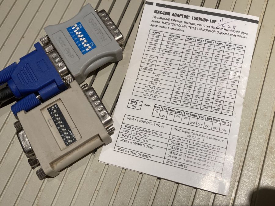
If you’re the happy owner of a vintage Apple system like a 1989 Macintosh IIci you may know the pain of keeping working monitors around. Unless it’s a genuine Apple-approved CRT with the proprietary DA-15-based video connector, you are going to need at least an adapter studded with DIP switches to connect it to other monitors. Yet as [Steve] recently found out, the Macintosh’s rather selective use of video synchronization signals causes quite a headache when you try to hook up a range of VGA-equipped LCD monitors. A possible solution? Extracting the sync signal using a Texas Instruments LM1881 video sync separator chip.

Much of this trouble comes from the way that these old Apple systems output the analog video signal, which goes far beyond the physical differences of the DA-15 versus the standard DE-15 D-subminiature connectors. Whereas the VGA standard defines the RGB signals along with a VSYNC and HSYNC signal, the Apple version can generate HSYNC, VSYC, but also CSYNC (composite sync). Which sync signal is generated depends on what value the system reads on the three sense pins on the DA-15 connector, as a kind of crude monitor ID.

Theoretically this should be easy to adapt to, you might think, but the curveball Apple throws here is that for the monitor ID that outputs both VSYNC and HSYNC you are limited to a fixed resolution of 640 x 870, which is not the desired 640 x 480. The obvious solution is then to target the one monitor configuration with this output resolution, and extract the CSYNC (and sync-on-green) signal which it outputs, so that it can be fudged into a more VGA-like sync signal. Incidentally, it seems that [Steve]’s older Dell 2001FP LCD monitor does support sync-on-green and CSYNC, whereas newer LCD monitors no longer list this as a feature, which is why now more than a passive adapter is needed.

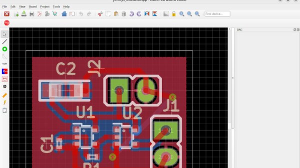
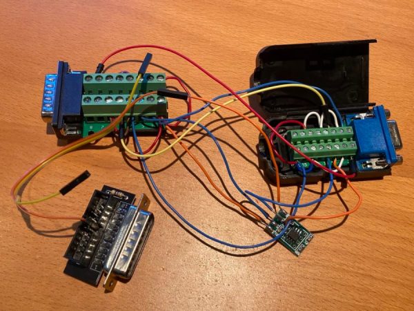
Although still a work-in-progress, so far [Steve] has managed to get an image on a number of these newer LCDs by using the LM1881 to extract CSYNC and obtain a VSYNC signal this way, while using the CSYNC as a sloppy HSYNC alternative. Other ICs also can generate an HSYNC signal from CSYNC, but those cost a bit more than the ~USD$3 LM1881.

Sine-wave Speech Demonstrates An Auditory One-way Door

Sine-wave speech can be thought of as a sort of auditory illusion, a sensory edge case in which one’s experience has a clear “before” and “after” moment, like going through a one-way door.

Sine-wave speech (SWS) is intentionally-degraded audio. Here are the samples, and here’s what to do:

  1. Choose a sample and listen to the sine-wave speech version (SWS). Most people will perceive an unintelligible mix of tones and beeps.
  2. Listen to the original version of the sentence.
  3. Now listen to the SWS version again.

Most people will hear only some tones and beeps when first listening to sine-wave speech. But after hearing the original version once, the SWS version suddenly becomes intelligible (albeit degraded-sounding).

These samples were originally part of research by [Chris Darwin] into speech perception, but the curious way in which one’s experience of a SWS sample can change is pretty interesting. The idea is that upon listening to the original sample, the brain — fantastic prediction and learning engine that it is — now knows better what to expect, and applies that without the listener being consciously aware. In fact, if one listens to enough different SWS samples, one begins to gain the ability to understand the SWS versions without having to be exposed to the originals. In his recent book The Experience Machine: How Our Minds Predict and Shape Reality, Andy Clark discusses how this process may be similar to how humans gain fluency in a new language, perceiving things like pauses and breaks and word forms that are unintelligible to a novice.

This is in some ways similar to the “Green Needle / Brainstorm” phenomenon, in which a viewer hears a voice saying either “green needle” or “brainstorm” depending on which word they are primed to hear. We’ve also previously seen other auditory strangeness in which the brain perceives ever-increasing tempo in music that isn’t actually there (the Accelerando Illusion, about halfway down the list in this post.)

Curious about the technical details behind sine-wave speech, and how it was generated? We sure hope so, because we can point you to details on SWS as well as to the (free) Praat software that [Chris] used to generate his samples, and the Praat script he wrote to actually create them.

Implementing Commodore’s IEC Bus Protocol On A KIM-1 Single Board Computer

Although the PET is most likely the more well-known of Commodore’s early computer systems, the KIM-1 (Keyboard Input Monitor) single board computer was launched a year prior, in 1976. It featured not only the same MOS 6502 MPU as later Commodore systems, but also an MCS6530 PIO IC that contained the ROM, RAM and programmable I/O, reminiscent of later I/O chips on Commodore systems. As the KIM-1 was only designed to be used with an external tape drive (and a terminal for fancy users), adding a floppy drive like the ubiquitous 1541 with its IEC bus interface was not a first-party accessory. How the IEC bus can be retrofitted to a KIM-1 system is demonstrated in this video by the Commodore History channel.

The Commodore KIM-1 hardware is almost directly compatible with the C64 hardware. (Credit: Commodore History on YouTube)

What is most notable is just how similar the KIM-1 hardware is to later PET and VIC hardware, with the CIA and PIO ICs featuring the same requisite pins for this purpose, and requiring only the addition of an inverting (SN7406) IC and an EPROM featuring the new code to support the proprietary Commodore IEC bus protocol, which was mostly pilfered byte-for-byte from a C64 kernal ROM.

With some creative breadboarding in place and using nothing more than the on-board LED display and keyboard matrix, it was then possible to write to the inserted floppy disk, and also to read back from it. What’s interesting here is that this essentially replaces the tape drive as target for the KIM-1, which thus retains a lot of the original functionality, but with a big performance boost. While perhaps only interesting as an academic exercise, it’s definitely an interesting look at the early beginnings of what would blossom into the Commodore 64.

Continue reading “Implementing Commodore’s IEC Bus Protocol On A KIM-1 Single Board Computer”

Playing The Guitar Of DOOM

Over the years, we’ve seen DOOM run on pretty much everything from an 8088 to a single keycap. We’ve also written up one or two controllers, but we don’t think we’ve ever seen anything like this — playing DOOM with an electric guitar.

The guitar in question is a Schecter Hellraiser Deluxe, which seems like a great choice to us. In order to get the notes to control the game, [DOS Storm] converted a handful of notes to MIDI using a VST plugin called Dodo MIDI 2 and the Reaper DAW. Then it was a matter of converting MIDI to keystrokes. This took two programs — loopMIDI to do take the MIDI data and route it elsewhere, and MIDIKey2Key to actually convert the MIDI to the keystrokes that control DOOM.

The result is that the notes that move Doomguy around are mostly in an A-major bar chord formation, with some controls up in the solo range of the fret board. Be sure to check out the demo video below and watch [DOS Storm] clear level one in a fairly impressive amount of time, considering their controller is a guitar.

That key cap isn’t even the most ridiculous thing we’ve seen DOOM running on. It’s probably a toss-up between that and the LEGO brick.

Continue reading “Playing The Guitar Of DOOM”

Hats Off To Another Weird Keyboard From Google Japan

As portable as keyboards have gotten, you still need some place to put the thing — some kind of bag for travel, and a flat surface for using it. Well, it doesn’t get much more portable than a hat keyboard, now does it?

Every October 1st, Google Japan likes to celebrate the 101-key keyboard by building something revolutionary off the top of their heads. (10/1… 101… get it?) This year was no exception — they created the GCAPS, a ballcap-like device with a single switch inside.

In order to use it, you spin the hat left and right until the desired character is reached, and the rotation is detected by a gyroscope. Then you press down on the top of the hat to send the key codes via Bluetooth.

Under the hood, the hat uses an M5Stick C Plus and, to our dismay, a micro switch that wasn’t even made by Cherry. Oh well —  we landed on the clicky side, so that’s great in our book. Surprisingly, there exists a skull cap/hat skeleton thing on which to build a platform for pressing down on the switch. Just like the teaboard and the long boi keyboards, this thing is completely open source.

Since it types in Japanese, there’s no word on whether it types in all caps, though we like to think that it would given the object it represents. Be sure to check out the product reveal video after the break.

Continue reading “Hats Off To Another Weird Keyboard From Google Japan”

Try It Out

It’s like Star Wars versus Star Trek at a SciFi convention, or asking creamy or chunky at the National Peanut Butter Appreciation Festival. (OK, we made that one up.) When Jenny reviewed the 1.0 version of LibrePCB, it opened the floodgates. Only on Hackaday!

Of course it makes sense that in a community of hardware hackers, folks who are not unfamiliar with the fine art and engineering of designing their own PCBs, have their favorite tools. Let’s face it, all PCB design software is idiosyncratic, and takes some learning. But the more fluent you are with your tool of choice, the more effort you have invested in mastering it, leading to something like the sunk-cost phenomenon: because you’ve put so much into it, you can’t think of leaving it.

The beauty of open-source software tools is that there’s almost nothing, aside from your own psychology, stopping you from picking up another PCB program, kicking the proverbial tires with a simple design, and seeing how it works for you. That’s what Jenny did here, and what she’s encouraged me to do. Whether it’s beginner-friendly Fritzing (also recently in version 1.0), upstarts LibrePCB or Horizon EDA, heavyweight champion KiCAD, or the loose-knit conglomeration of tools in coralEDA, you have enough choices that something is going to fit your PCB hand like a glove.

I certainly wouldn’t risk a swap up to a new tool on something super complicated, or something with a tight deadline, but why not start up a fun project to test it out? Maybe follow Tom Nardi’s lead and make a Simple Add-on, for a badge or just as a blinky to put on your desk? Don’t be afraid to try something new!

Control Tricks For Tailsitters

An RC VTOL aircraft always makes for a compelling project, but ensuring the transition between hover and forward flight can be quite challenging. In the video after the break, [Nicholas Rehm] demystifies of the flight control algorithm required for a VTOL tailsitter.

Tailsitters are one of the simplest VTOL arrangements, the testbed here being a simple foam KF airfoil wing with two motors and two servo-controlled elevons. As with almost all his projects [Nicholas], uses of his open-source dRehmFlight flight controller to demonstrate the practical implementation of the control algorithm.

Three major factors that need to be simultaneously taken into account when transitioning a tailsitter VTOL. First off, yaw becomes roll, and vice versa. This implies that in hover mode, elevons have to move in opposite directions to control yaw; however, this same action will make it roll in forward flight. The same applies for differential thrust from motors — it controls roll in hover and yaw in forward flight. Nevertheless, this change of control scheme only works if the flight controller also alters its reference frame for “level” flight (i.e., flips forward 90°). As [Nicholas] demonstrates, failing to do so results in a quick and chaotic encounter with the ground.

With these adjustments made, the aircraft can transition to forward flight but will oscillate pitch-wise as it overcorrects while trying to maintain stable flight; this is due to PID gains – 3rd factor. The deflection required by control surfaces is much more aggressive during hover mode; thus PID gains need to be reduced during forward flight. A final improvement involves adding a brief delay when switching modes for smoother rotation.

For more interesting VTOL configurations, check out [Tom Stanton]’s RC V-22 Osprey, and this solar recharging trimotor

Continue reading “Control Tricks For Tailsitters”