One thing that always provokes spirited debate around the Hackaday bunker is just how dangerous is it to use 3D printed plastic in contact with food. We mostly agree it isn’t a good thing, but we also know some people do it regularly and they don’t drop dead instantly, either. [Jakub] decided to do some testing and make some recommendations. There’s even a video explaining the results.
Unlike a lot of what we’ve read about this topic in the past, [Jakub’s] post is well-researched and does actual testing including growing bacteria cultures from cups used for milk. He starts out identifying the EU and US regulations about what you can call food-grade. There’s also recognition that while a base plastic might be safe for contact with food, there’s no way to know exactly what additives and other things are in the plastic to change its properties and color.
Even when we share the design files for open source hardware, the step between digital files and a real-world mechatronics widget is still a big one. That’s why I set off on a personal vendetta to find ways to make that transfer step easier for newcomers to an open source mechantronics project.
Today, I want to spill the beans on one of these finds: part numbers, and showcase how they can help you share your project in a way that helps other reproduce it. Think of part numbers as being like version numbers for software, but on real objects.
I’ll showcase an example of putting part numbers to work on one of my projects, and then I’ll finish off by showing just how part numbers offer some powerful community-building aspects to your project.
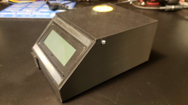
3D printers are capable of creating complex geometries with a minimum of fuss, but one of the tradeoffs is the long period of time it takes to print a part. Often, printers are left to run for many hours with a minimum of supervision to complete their tasks. This can leave printers idling for long periods of time after their work is finished. Noting this, [TheGrim] put together the Advanced Printer Control.
The aim of the APC is to monitor 3D printers, and shut them off when their work is complete. The aim is to avoid leaving printers running for hours after their prints are finished, which causes needless wear on fans and screens which can have a limited life. This is achieved by putting an ESP8266 in charge of the printer’s AC power supply, via a triac. It measures the current drawn by the printer when idling and in use to set a baseline. Then, whenever the printer drops back to idle levels, a timer begins. When the timer runs out, the printer is switched off. There’s also an option to automatically trigger shutdown with an I/O pin, too.
[Jesse]’s modification doesn’t affect the laser beam itself; it is an improvement on the air assist, which is the name for a constant stream of air that blows away smoke and debris as the laser burns and vaporizes material. An efficient air assist is one of the keys to getting nice clean laser cuts, but [Jesse] points out that a good quality air assist isn’t just about how hard the air blows, it’s also about how smoothly it does so. A turbulent air assist can make scorch marks worse, not better.
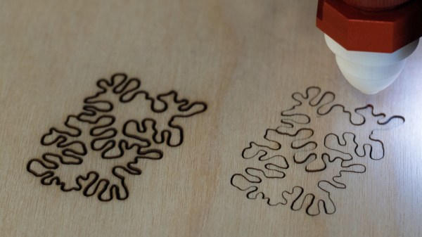
3D-printed nozzle to promote laminar air flow on the left, stock nozzle on the right.
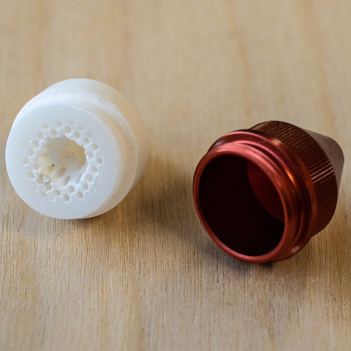
As an experiment to improve the quality of the air flowing out the laser nozzle, [Jesse] researched ways to avoid turbulence by creating laminar flow. Laminar flow is the quality of a liquid having layers flowing past one another with little or no mixing. One way to do this is to force liquid through individual, parallel channels as it progresses towards a sharply-defined exit nozzle. While [Jesse] found no reference designs of laminar flow nozzles for air assists, there were definitely resources on making laminar flow nozzles for water. It turns out that interest in such a nozzle exists mainly as a means of modifying Lonnie Johnson’s brilliant invention, the Super Soaker.
Working from such a design, [Jesse] created a custom nozzle to help promote laminar flow. Sadly, a laser cutter head carries design constraints that make some compromises unavoidable; one is limited space, and another is the need to keep the laser’s path unobstructed. Still, after 3D printing it in rigid heat-resistant resin, [Jesse] found a dramatic improvement in the feel of the air exiting the nozzle. Some test cuts confirmed a difference in performance, which results in a noticeably cleaner kerf without scorching around the edges.
One of the things [Nervous System] does is make their own custom puzzles, so any improvement to laser cutting helps reliability and quality. When production is involved, just about everything matters; a lesson [Nervous System] shared when they discussed making the best plywood for creating their puzzles.
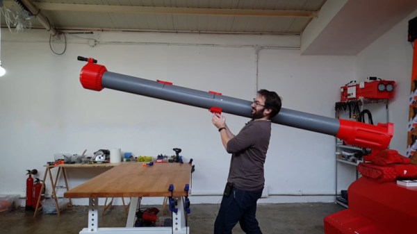
Nerf blasters are a fun toy, often confiscated from children once they hit one too many precious ornaments around the home in the midst of battle. [Ivan Miranda] is bigger than most children however, and set about building a much larger blaster.
The bazooka-like design uses a several meters of 160mm PVC pipe, firing “darts” constructed out of foam yoga rollers and buffing pads. The build uses a littany of 3D printed components in its construction, both as part of the firing mechanism and as jigs to help machine the pipe. A large plunger is used to propel the darts, which is pulled back against the tension of thick rubber tubes before being released by the trigger mechanism.
It’s an intimidating device, to be sure. However, we suspect its short range, huge size, and slow reload time should stop it from breaking the meta-game at your local Nerf battles. That said, we still wouldn’t want to take a shot from this bad boy to the head. Hackers do love a good Nerf build, and they’re particularly popular in sentry applications. Video after the break.
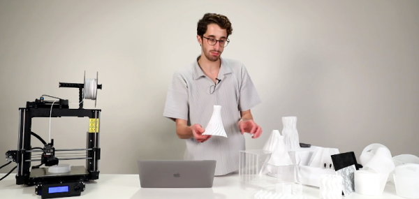
Normally, a 3D printer that under extrudes is a bad thing. However, MIT has figured out a way to deliberately mix full extrusions with under extruded layers to print structures that behave more like cloth than normal 3D printed items. The mesh-like structure apparently doesn’t require any modification to a normal 3D printer, just different software to create special code sequences to create the material.
Called DefeXtiles, [Jack Forman] is producing sheets and complex structures that appear woven. The process is known as “blob-stretch” because of the way the plastic makes blobs connected by fine filaments of plastic.
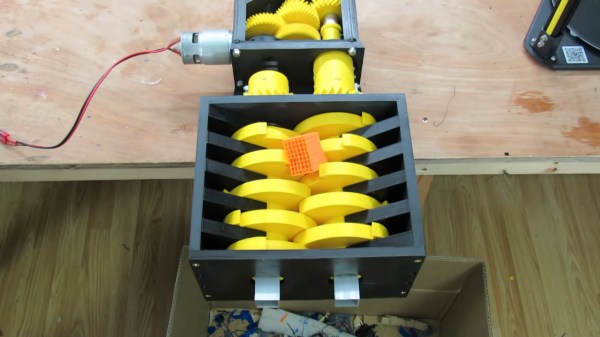
[Brian Brocken] is at it again, building mechanisms that are as striking in their aesthetic as they are in their function. This time around, he’s extended a project we recently featured by adding a menacing 3D-printed shredder attachment. When you hear “3D-printed shredder” you think that paper is all you’ll be able to feed it, but this beast can eat its own by shredding parts from failed prints.
His original goal in building the high-torque 3D-printed gear box we looked at back in August was to show that 3D printed parts can be functional and not merely decorative. Using it as a winch to pull a car did a good job of that, but this goes much further. The very nature of shredder blades is to tear apart objects, but the forces that destroy those things are also present on the shredder parts themselves. Still, as you can see in the video below, the counter-rotating twin-shaft shredder mechanism does its work without catastrophic damage to the blades which were printed with “least 25 percent infill for the structural parts”, and up to five outer perimeters.
The result is a shredder that can gobble up small pieces of failed prints, in addition to chewing on paper, cardboard, and polystyrene with ease. [Brian] does show a few failures along the way, all in the gearbox itself. The first was a defect in the housing that let an gear shaft pop loose and was fixed up with a reprint. The second is a catastrophic gear failure when trying to shred a soda bottle. This is not surprising as PET is quite tough and not brittle like the waste prints were. The shredder teeth got bogged down, and the power of the motor strips teeth from a few gears. But when working, it’s oddly satisfying to watch that powerful gear ratio chip away at sacrificial materials.