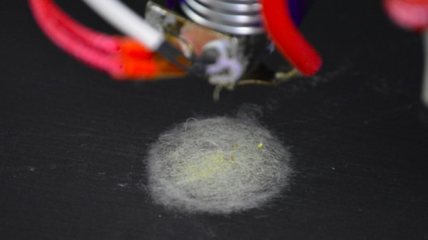
We are all used to desktop 3D printers that extrude molten plastic in layers to build up finished items. A pair of researchers at the Human-Computer Interaction Institute at Carnegie Mellon University, [Michael Rivera] and [Scott Hudson], have added another capability to their printer: electrospinning of textiles.
Electrospinning is a technique in which an extruded material is accelerated from the extruder by an electrostatic charge to form an extremely thin fibre. By applying a many-kilovolt charge between the extruder and the bed, they can create a fibre and lay it down into a mesh from a height to create a felt-like fabric. The same extruder can also produce conventional solid prints, allowing the creation of composite fabric and solid items. They demonstrate a variety of prints including a folding mobile phone stand, a woven lamp, and an interactive wooly sheep, which along with others can be seen in the video below the break.
The full paper can be downloaded as a PDF, and makes for very interesting reading. The voltages involved mean that your Prusa clone may not have this capability any time soon, but we look forward to the moment when desktop electrospinning is a feature on affordable 3D printers.
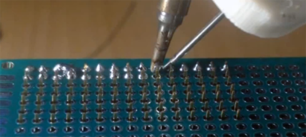
What do you do if you have to solder thousands of through-hole parts? The expensive, professional way of doing this is running the boards through a wave soldering machine, or a machine with a fancy CNC solder fountain. The amateur way of soldering thousands of through-hole joints is putting some boards on the workbench and sitting down with a soldering iron. There is nothing in between; you’re either going to go with full automation for a large soldering job, or you’re doing it completely manually. That’s the problem this soldering robot solves. It’s a small, cheap, but still relatively capable soldering robot built out of a 3D printer.
This project is a solution to the development hell of the OpenScan project. This project is built around a small, simple printed circuit board that uses several 0.1″ female headers to connect an Arduino and motor drivers. Soldering them by hand is simply boring, and 3D printers are cheap, so the great mind behind this project decided to use a printer to pump out solder.
The modifications to the printer include a mount for a TS100 soldering iron and a modified filament extruder that pushes a spool of solder through a PTFE tube. The GCode for this soldering job was created manually, but you could also use a slicer instead. After 20 hours of development, the ‘success rate’ – however that is defined – is between 60-80%. That needs to get up to four or five nines before this DIY soldering robot is practical but this is a decidedly not-bad result for a few hours of tinkering.
This printer mod works great for the use case of stuffing a few 0.1″ headers into a board and letting a robot automatically solder the joints, but this printer will run into a problem with the general case of soldering a lot of randomly-shaped through hole parts. You need to actually hold the parts up against the board while soldering. There’s an easy solution to this problem: just flip the 3D printer upside down. This hack of a cheap 3D printer is so, so close to being a great solution to soldering thousands of through-hole parts quickly and easily, and we’re looking forward to seeing where the community takes this idea. You can check out the video demo below.
If you can ride a bike with no handlebars, no handlebars, no handlebars, you can do just about anything. You can take apart a remote control, and you can almost put it back together. You can listen in on a two meter repeater and you can build a GPS module speedometer. That’s what [Jeremy Cook] did with just a few parts, a little 3D design, and some handy zip ties to hold it onto the handlebars, the handlebars.
The electronics for this build are relatively simple, based on an Arduino Pro Mini because that’s just about the smallest readily available development board you’ll be able to find. To this is a LiPo, a LiPo charging circuit, a GPS module, and a single RGB LED. The code gets some data from the GPS module and figures out a speed. This is then translated into a color — red, yellow, or green depending on whether you’re stationary, below 5 km/h, or above 5 km/h.
All these electronics are stuffed into a 3D-printed enclosure. The majority of the enclosure is printed in black, with a translucent top that serves as a great diffuser for the LED. Just two zip ties hold this GPS speedometer onto the handlebars, and from the video below, everything looks great. The GPS module does take some time to get data at first, but that’s a common problem with GPS units that have been powered off for a few days. If only someone made a GPS module that could keep time with no metronome, with no metronome.
If you own a 3D printer, you’ve heard of Thingiverse. The MakerBot-operated site has been the de facto model repository for 3D printable models since the dawn of desktop 3D printing, but over the years it’s fallen into a state of disrepair. Dated and plagued with performance issues, many in the community have been wondering how long MakerBot is still going to pay to keep the lights on. Alternatives have popped up occasionally, but so far none of them have been able to amass a large enough userbase to offer any sort of real competition.
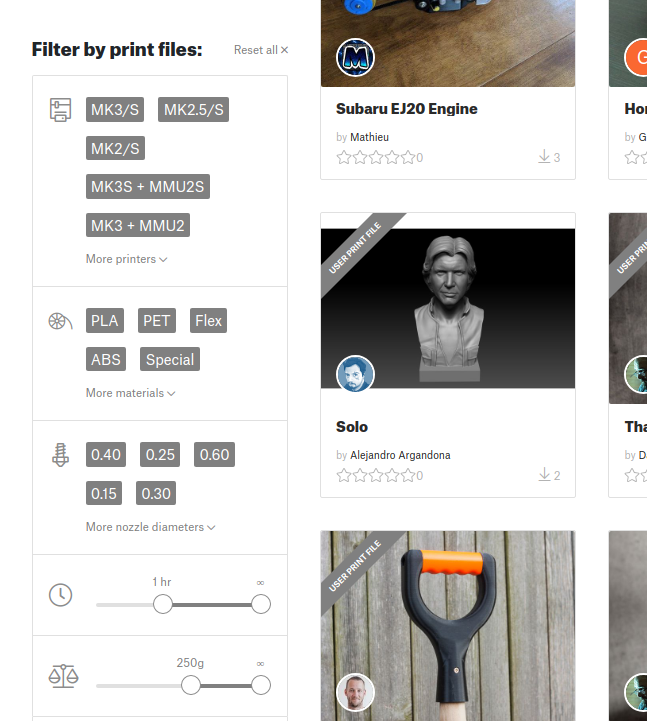
Sorting models by print time and material required.
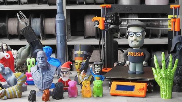
But that might soon change. [Josef Průša] has announced a revamped community for owners of his 3D printers which includes a brand-new model repository. While clearly geared towards owners of Prusa FDM printers (support for the new SLA printer is coming at a later date), the repository is not exclusive to them. The immense popularity of Prusa’s products, plus the fact that the repository launched with a selection of models created by well known designers, might be enough to finally give Thingiverse a run for its money. Even if it just convinces MakerBot to make some improvements to their own service, it would be a win for the community.
The pessimists out there will say a Prusa-run model database is ultimately not far off from one where MakerBot is pulling the strings; and indeed, a model repository that wasn’t tied to a particular 3D printer manufacturer would be ideal. But given the passion for open development demonstrated by [Josef] and his eponymous company, we’re willing to bet that the site is never going to keep owners of other printers from joining in on the fun.
That being said, knowing that the users of your repository have the same printer (or a variant, at least) as those providing the designs does have its benefits. It allows for some neat tricks like being able to sort designs by their estimated print time, and even offers the ability to upload and download pre-sliced GCode files in place of traditional STLs. In fact, [Josef] boasts that this is the world’s only repository for ready-to-print GCode that you can just drop onto an SD card and print.
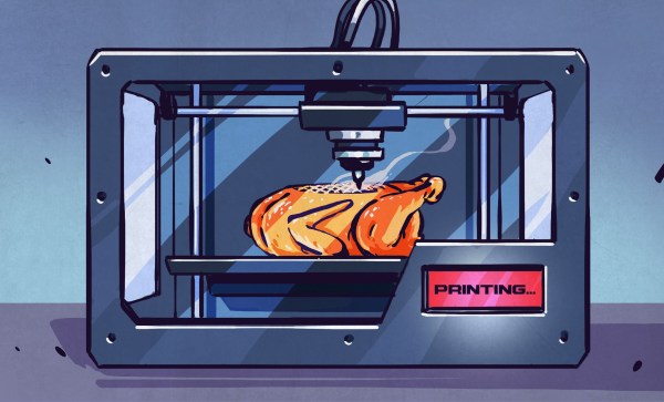
A video has been making the rounds on social media recently that shows a 3D printed “steak” developed by a company called NovaMeat. In the short clip, a machine can be seen extruding a paste made of ingredients such as peas and seaweed into a shape not entirely unlike that of a boot sole, which gets briefly fried in a pan. Slices of this futuristic foodstuff are then fed to passerby in an effort to prove it’s actually edible. Nobody spits it out while the cameras are rolling, but the look on their faces could perhaps best be interpreted as resigned politeness. Yes, you can eat it. But you could eat a real boot sole too if you cooked it long enough.
To be fair, the goals of NovaMeat are certainly noble. Founder and CEO Giuseppe Scionti says that we need to develop new sustainable food sources to combat the environmental cost of our current livestock system, and he believes meat alternatives like his 3D printed steak could be the answer. Indeed, finding ways to reduce the consumption of meat would be a net positive for the environment, but it seems his team has a long way to go before the average meat-eater would be tempted by the objects extruded from his machine.
But the NovaMeat team aren’t the first to attempt coaxing food out of a modified 3D printer, not by a long shot. They’re simply the most recent addition to a surprisingly long list of individuals and entities, not least of which the United States military, that have looked into the concept. Ultimately, they’ve been after the same thing that convinced many hackers and makers to buy their own desktop 3D printer: the ability to produce something to the maker’s exacting specifications. A machine that could produce food with the precise flavors and textures specified would in essence be the ultimate chef, but of course, it’s far easier said than done.
As 3D printing becomes more and more used in a wide range of fields, medical science is not left behind. From the more standard uses such as printing medical equipment and prosthetics to more advanced uses like printing cartilages and bones, the success of 3D printing technologies in the medical field is rapidly growing.
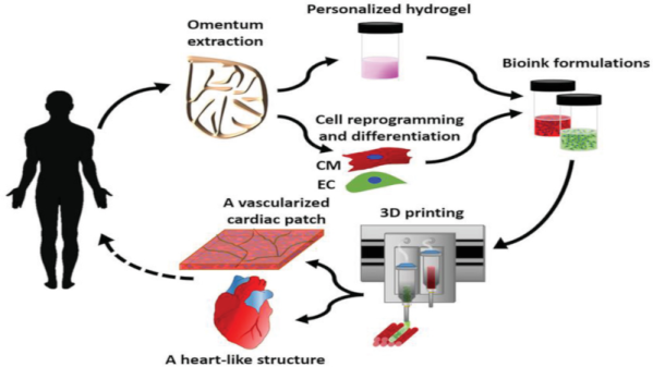
One of the last breakthrough is the world’s first 3D vascularised engineered heart using the patient’s own cells and biological materials. Until now, scientists have only been successful in printing only simple tissues without blood vessels. Researchers from Tel Aviv University used the fatty tissue from patients to separate the cellular and acellular materials and reprogrammed the cells become pluripotent stem cells. The extracellular matrix (ECM) was processed into a personalized hydrogel that served as the basis from the print.
This heart is made from human cells and patient-specific biological materials. In our process these materials serve as the bioinks, substances made of sugars and proteins that can be used for 3D printing of complex tissue models… At this stage, our 3D heart is small, the size of a rabbit’s heart, but larger human hearts require the same technology.
After being mixed with the hydrogel, the cells were efficiently differentiated to cardiac or endothelial cells to create patient-specific, immune-compatible cardiac patches with blood vessels and, subsequently, an entire heart that completely matches the immunological, cellular, biochemical and anatomical properties of the patient. The difficulty of printing full-blown organs were being tackled for a long time and we already talked about it in the past.
The development of this technology may completely solve both the problem of organ compatibility and organ rejection.
We’ve seen plenty of methods to create stronger 3D prints, from using carbon fiber filament to simply printing the part in a way that the layers of the print are orthogonal to the direction of force. We’ve even seen casting carbon fiber bars into 3D prints, but of course that will only work with straight parts. [Brauns]’ technique uses steel wire, embedded into the print itself, and from some testing there’s about a 50% increase in strength of the part.
The process of embedding a steel cable into a 3D printed part is simply taking apart the model and putting a channel in for the cable. At a specific layer height, the printer is stopped, the steel cable is embedded with the help of a soldering iron, and the printer continues doing its thing.
There’s a slight amount of Gcode hacking to make this happen, and the process of embedding a steel cable into a print is a bit finicky. Still, if you want stronger 3D prints, there are worse ways to do it, and certainly less effective ways of doing it. You can check out the video for this technique below.