With all the tools and services available to us these days, it’s hard to narrow down a set of skills that the modern hacker or maker should have. Sure, soldering is a pretty safe bet, and most projects now require at least a little bit of code. But the ability to design 3D printable parts has also become increasingly important, and you could argue that knowledge of PCB design and production is getting up there as well. With home laser cutters on the rise, a little 2D CAD wouldn’t hurt either. So on, and so on.
If you ever wanted an example of the multitude of skills that can go into a modern hardware project, take a look at this gorgeous Vacuum Fluorescent Display (VFD) tube calculator built by [oskar2517]. As fantastic as the final product is, we were particularly impressed with everything it took to get this one over the finish line.
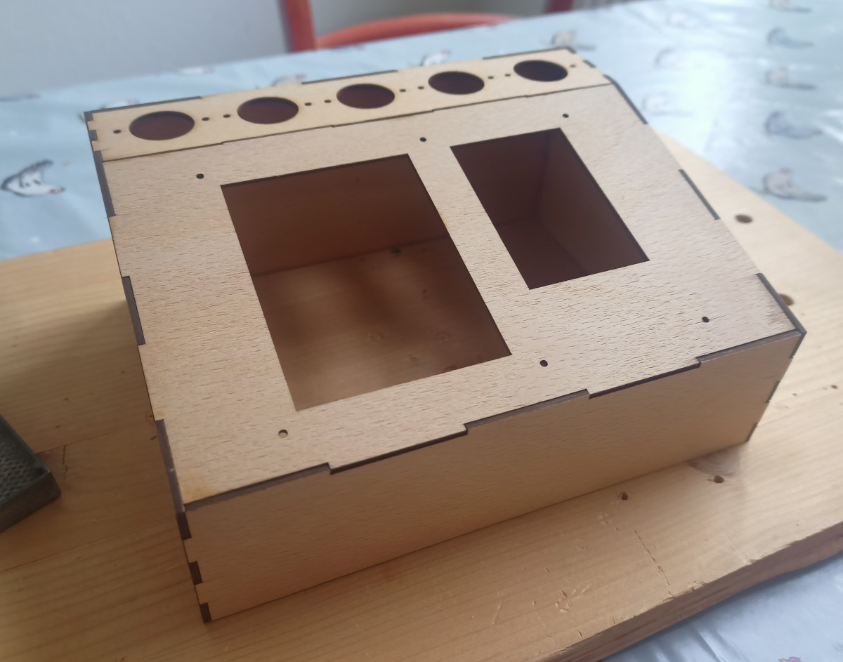
It’s got it all: 3D printed parts, a laser cut wooden frame, a custom PCB, and even a bit of old school woodworking. To top it all off, the whole thing has been meticulously documented.
But what’s perhaps most impressive here is that [oskar2517] was approaching most of these techniques for the first time. They had never before worked with IV-12 tubes, designed an enclosure in 3D, had parts laser cut, applied wood veneer, or designed a custom PCB. They did have solid experience writing code in C at least, which did make developing the Arduino firmware a bit easier.
Although they might look outwardly similar, VFD tubes like the IV-12 are easier to work with than Nixie tubes thanks to their lower operating voltage. That said, a look through our archives shows that projects using Nixies outnumber VFD tubes by nearly four to one, so there’s no shortage of folks willing to take on the extra effort for that sweet warm glow.