Presenting The Internet Of Trash Cans !

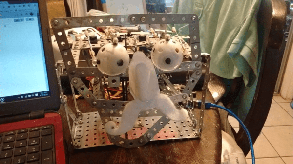
This was gonna happen – sooner or later. [matthewhallberg] built a “Smart” trash can that is connected to the Internet and can be controlled by its own Android App. We’re not sure if the world needs it, but he wanted one and so built it. He started it out on a serious note, but quickly realized the fun part of this build – check out his funny Infomercial style video after the break.

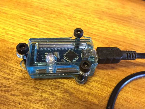
trash_can_02The build itself is uncomplicated and can be replicated with ease. A servo motor helps flip the lid open and close. This is triggered by an ultrasonic ping sensor, which responds when someone waves a hand in front of the trash can. A second ping sensor helps inform the user when it is full and needs to be emptied. A Leonardo with the Idunio Yun shield helps connect the trash can to the internet. An mp3 shield connected to a set of powered computer speakers adds voice capability to the trash can, allowing it to play back pre-recorded sound clips. Finally, a Bluetooth module lets him connect it to an Android phone and the companion app controls the trash can remotely.

For the IoT side of things, [matthewhallberg] uses a Temboo account to send an email to the user when the trash can is full. The Arduino sketch, a header file to configure the Temboo account, and the Android application can all be downloaded from his blog. If this project inspires you, try building this awesome Robotic trash can which catches anything that you throw near it  or read the barcodes off the trash being thrown out and update the grocery list.

Continue reading “Presenting The Internet Of Trash Cans !”

Fingerprint Garage Door Won’t Open Every Time A Neighbor Microwaves A Burrito

With three kids, including himself, [Dave] faced the very real likelihood of someone absent-mindedly leaving the garage door open and being robbed blind. Rather than installing some plebeian solution, he compiled a feature list. And what a feature list it is!

The garage door needed to notify him of its status with strategically placed LEDs around the house, and give him full control on his devices. He wanted to open and close it using his existing key-code entry system. Lastly, it would be extra-cool if he could add some biometrics to it; in this case, a fingerprint sensor.

The core hardware is the staple Arduino augmented with a fingerprint module, a touch screen, some vitamins, and a WiFi break-out. He also worked up some casings in tinkercad: one for the indoor hardware, another with a flip cover for the outdoor fingerprint scanner.

We think [Dave] has accomplished what he set out to. We can just picture the would-be-thief staring at the finger print scanner and moving their operation one house over where the world is simpler. Video after the break.

Continue reading “Fingerprint Garage Door Won’t Open Every Time A Neighbor Microwaves A Burrito”

SDRAM Logic Analyzer Uses An AVR And A Dirty Trick

We often see “logic analyzer” projects which are little more than microcontrollers reading data as fast as they can, sending it to a PC, and then plotting the results. Depending on how fast the microcontroller is, these projects range from adequate to not very useful.

At first glance, [esot.eric’s] logic analyzer project has an AVR in it, so it ought to be on the low end of the scale. Then you look at the specs: 32 channels at 30 megasamples per second. How does that work with an AVR in it?

The answer lies in the selection of components. The analyzer uses a 128MB SDRAM DIMM (like an older PC might use for main memory). That makes sense; the Arduino can’t store much data internally. However, it isn’t the storage capacity that makes this choice critical. It seems [esot.eric] has a way to make the RAM “free run”.

The idea is to use the Arduino (or other host microcontroller) to set up the memory. Some of the memory’s output bits feedback to the address and data lines. Then the microcontroller steps aside and the SDRAM clocks samples into its memory by itself at the prevailing clock rate for the memory.

Continue reading “SDRAM Logic Analyzer Uses An AVR And A Dirty Trick”

Laser PCB Exposer Built From CD-ROM Drives

[Neumi] has built a CNC Laser using CD-ROM drives as the X and Y motion platforms. The small 405nm laser can engrave light materials like wood and foam. The coolest use demonstrated in the video is exposing pre-coated photo-resist PCBs.

With $61 US Dollars (55 Euro) for the Arduino, stepper drivers, and a laser in the project, [Nuemi] got a pretty capable machine after adding a few parts from the junk bin. He wanted to avoid using existing software in order to learn the concepts behind a laser engraver. In the end, he has a working software package which can send raster scans to an Arduino mega. The mega then controls the sync between the stepper and laser firings. The code is available on GitHub.

The machine can do a 30x30mm PCB in 10 minutes. It’s not about to set a record, but it’s cool and not at all bad for the price. You can see the failed PCBs lined up in the video from the initial tuning, but the final one produced a board very equivalent to the toner transfer method. Video after the break.

Continue reading “Laser PCB Exposer Built From CD-ROM Drives”

Petite Package Provides Powerful Robot

The Robot Operating System (ROS) is typically associated with big robots but [Grassjelly] decided to prove differently by creating Linorobot. This small, differential drive robot is similar in appearance to many small Arduino based robots often used for line following. Linorobot packs a lot more computing power with a Teensy 3.1 connected to a Radxa Rock Pro. The Teensy handles the motors, reading their encoders, and acquisition of IMU data.

The Radxa, new to us here at Hackaday, is a single board computer based on the quad-core ARM Cortex-A9 1.6 GHz CPU. It may not have been seen on our pages but if you’re at Hackaday Belgrade you can attend a session on building a cluster using it. The ability to run Linux is key to using ROS, which is an open source system for controlling robots. With the Radxa running ROS it interfaces directly to the Neato XV-11 Lidar’s dedicated controller board.

The Linorobot packs into a small robot the capabilities usually seen in much larger and expensive robots such as the Turtlebot 2. With this diminutive robot hackers can learn about doing SLAM (Simultaneous Localization and Mapping) and autonomous navigation, plus the other capabilities of ROS.

[Grassjelly] has a tutorial on building the robot which is also a good introduce to ROS. He provides the software as open source. It’s an impressive project which provides a small, comparatively affordable robot for learning and working with ROS. A video of Linorobot SLAMing and navigating [Grassjelly’s] lab is after the break.

Continue reading “Petite Package Provides Powerful Robot”

Blinky LED Bike Bag

Bicycle riders can never be too visible: the more visible you are, the less chance there is someone will hit you. That’s the idea behind the Arduibag, a neat open-source project from [Michaël D’Auria] and [Stéphane De Graeve]. The project combines a joystick that mounts on the handlebars with a dot matrix LED display in a backpack. By moving the joystick, the user can indicate things such as that they are turning, stopping, say thank you or show a hazard triangle to warn of an accident.

The whole project is built from simple components, such as an Adafruit LED matrix and a Bluno (an Arduino-compatible board with built-in Bluetooth 4.0) combined with a big battery that drives the LED matrix. This connects to the joystick, which is in a 3D printed case that clips onto the handlebars for easy use. It looks like a fairly simple build, with the larger components being mounted on a board that fits into the backpack and holds everything in place. You then add a clear plastic cover to part of the backpack over the LED matrix, and you are ready to hit the road, hopefully without actually hitting the road.

Continue reading “Blinky LED Bike Bag”

Adventures In Small Screen Video

[Kevin] wanted to make something using a small CRT, maybe an oscilloscope clock or something similar. He thought he scored big with a portable black and white TV that someone threw away, but it wouldn’t power on. Once opened, he thought he found the culprit—a couple of crusty, popped capacitors. [Kevin] ordered some new ones and played with the Arduino TVout code while he waited.

The caps arrived, but the little TV still wouldn’t chooch. Closer inspection revealed that someone had been there before him and ripped out some JST-connected components. Undaunted, [Kevin] went looking for a new CRT and found a vintage JVC camcorder viewfinder on the electronic bay with a 1-1/8″ screen.

At this point, he knew he wanted to display the time, date, and temperature. He figured out how the viewfinder CRT is wired, correctly assuming that the lone shielded wire is meant for composite video. It worked, but the image was backwards and off-center. No problem, just a matter of tracing out the horizontal and vertical deflection wires, swapping the horizontal ones, and nudging a few pixels in the code. Now he just has to spin a PCB, build an enclosure, and roll his own font.

[Kevin]’s CRT is pretty small, but it’s got to be easier on the eyes than the tiniest video game system.