For those who haven’t addicted themselves to Super Hexagon yet, it’s pretty… addicting, to say the least. Normally this 80’s arcade-style game would run in a browser but some of the people at Club de Jaqueo in Buenos Aires decided to cram all of that into an Arduino. They didn’t stop there, though, and thought that it would work best with a POV display.
To navigate the intricate maze of blending a POV display with a fast-paced game like this, the group turned to the trusty Arduino Micro. After some frustration in the original idea, they realized that the game is perfectly suited for a POV display since it’s almost circular. The POV shouldn’t take up too much of the processing power of the Arduino, so most of the clock cycles can be used for playing the game. They couldn’t keep the original name anymore due to the lack of hexagon shape (and presumably copyrights and other legal hurdles), but the style of the original is well-preserved.
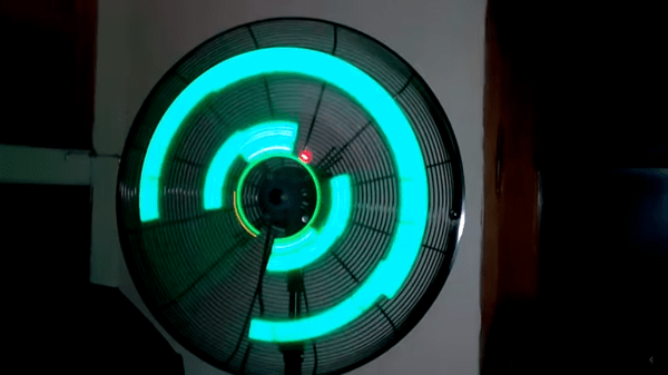
The group demonstrated their setup this past weekend, and the results are impressive judging by the video below. They’ve also released their source code and schematics as well, in case you have an old fan (or maybe even a bicycle?) lying around that is just begging to be turned into a mini-arcade game.