We’re big fans of the Arduboy here at Hackaday, but we’ll admit its tiny screen isn’t exactly ideal for long gaming sessions. There are some DIY builds of the open source handheld that use a larger SPI OLED display, though you’re relatively limited on what kind of changes can be made to the hardware before the games start balking. But as [Nick Bild] shows with his Arduboy home console, hacking the core system library opens up a lot of interesting possibilities.
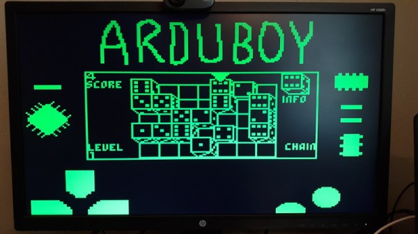
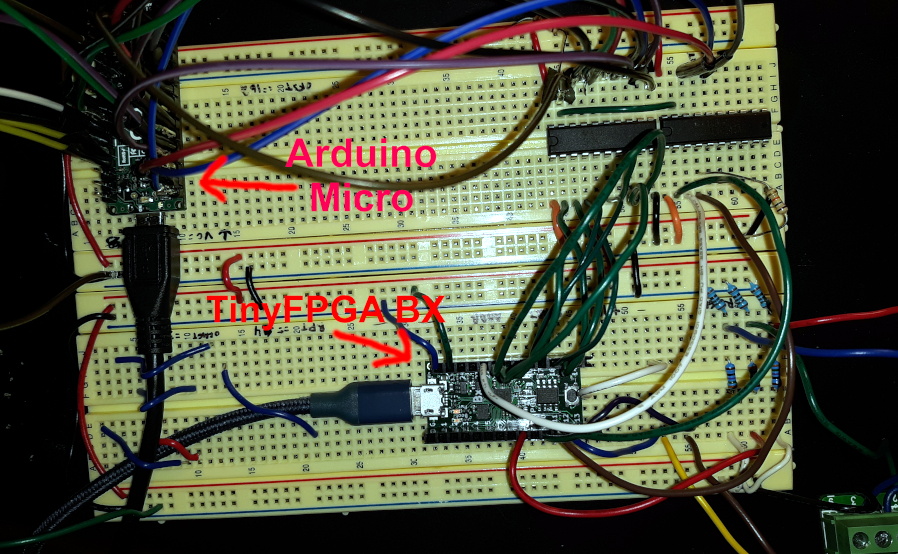
Games written for the Arduboy make use of a common library that handles all the low-level hardware stuff, which includes a display() function to push the graphical data out to an SPI-connected OLED display. What [Nick] has done is re-write that function to instead output to a custom VGA generator running on the TinyFPGA BX. He had to delete support for the Arduboy’s RGB LEDs because he needed the extra pins, but that shouldn’t cause much of a problem in terms of software support.
 This does mean that games need to be recompiled against the modified library to work on his hardware, but as the vast majority of Arduboy software is open source anyway, that’s not much of a problem. We particularly like the Super Game Boy style border you get around the display at no extra cost.
At this point the hardware looks less like a console and more like a breadboard filled with jumpers, so we’re interested in seeing this project taken to its logical conclusion. A custom PCB, enclosure, and possibly even support for using the original NES controllers would turn this into proper system worthy of any hacker’s game room. You could even put the games on custom cartridges if you wanted, though a flash chip that holds the system’s entire library would be quite a bit more convenient.