It might take you some time to understand what’s happening in the video that Hackaday alum [Moritz Sivers] shared with us. This is [Moritz]’s contribution for this year’s Pi Day – a machine that shows digits of Pi in a (technically, not quite) infinite loop, and shows us a neat trick we wouldn’t have thought of.
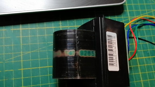
The two main elements of this machine are a looped piece of thermochromic foil and a thermal printer. As digits are marked on the foil by the printer’s heating element, they’re visible for a few seconds until the foil disappears from the view, only to be eventually looped back and thermally embossed anew. The “Pi digits calculation” part is offloaded to Google’s pi.delivery service, a π-as-a-Service endpoint that will stream up to 50 trillion first digits of Pi in case you ever need them – an ESP8266 dutifully fetches the digits and sends them off to the thermal printer.
This machine could print the digits until something breaks or the trillions of digits available run out, and is an appropriate tribute to the infinite nature of Pi, a number we all have no choice but to fundamentally respect. A few days ago, we’ve shown a similar Pi Day tribute, albeit a more self-sufficient one – an Arduino calculating and printing digits of Pi on a character display! We could’ve been celebrating this day for millennia, if Archimedes could just count a little better.
Continue reading “Celebrating The Infinity Of Pi Day With Thermochromic Foil”


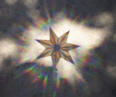 The design is straightforward, consisting of a 3D printed frame made of pieces glued together using QuickGrab glue. The pieces come together into a 7-segment star design, with a subtle 3D structure to it which helps add strength in addition to looking good.


